VCR RECORDING MODE
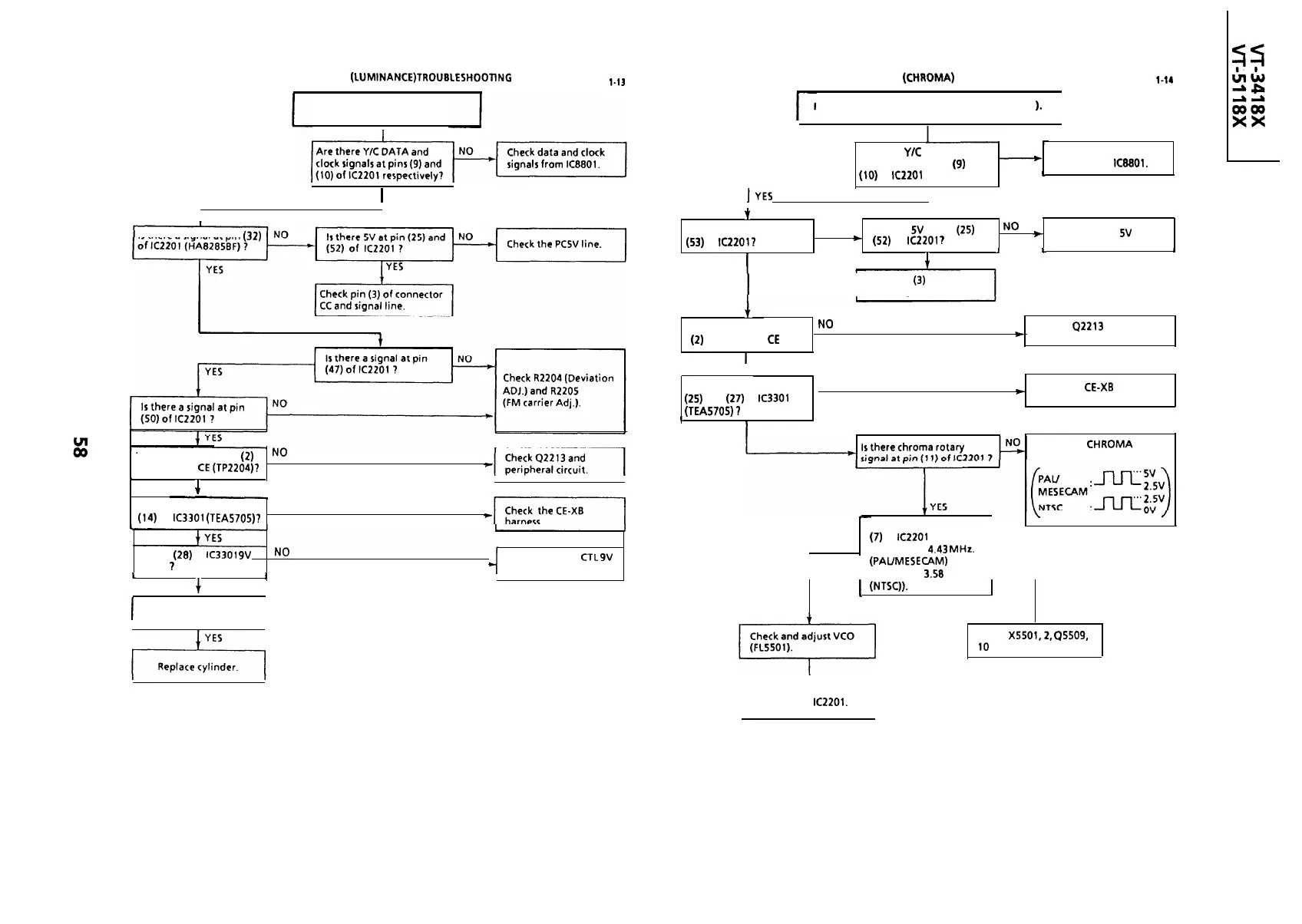
(LUMlNANCE)TROUBLESHOOTlNG
FLOW CHART NO.
l-13
VCR RECORDING MODE (CHROMA) TROUBLESHOOTING
FLOW CHART NO.
l-14
No record.
Record Is In black and white ( E-E color mode
1.
I
Are there
YJC
DATA and
NO
Check data and clock
clock signals at pins (9) and
-
signals from
IC8801.
(10)
of
IC2201
respectively?
1
1
YES
IYES
,
t
Is there a signal at pin
NO
Is there
SV
at pin
(25)
and .
No
*
(52)
of
IC2201
?
+
Check the PC
5V
line.
(53)
of
IC2201?
I
I L
J
L
8
1
YES
+
YES
Is there a signal at pin (32)
I
Check pin
(3)
of connector
CC and signal line.
+~
Is there a signal at pin
No
Check
42213
and
(2)
of connector
CE
7
*
peripheral circuit.
I I
1
YES
t ,
Is there a signal at pin
NO
(25)
and
(27)
of
IC3301
)
Check the
CE-XB
harness.
1
(TEA5705)
7
I
1
YES
Is there a signal at pin (2)
No
of connector
CE
(TP2204)?
Check the CHROMA
ROTARY line.
I
+
YES
J
I
I
-
NO
Is there a signal at pin
(14)
of
IC3301
(TEA5705)?
Check the signal at pin
L
(7)
of
IC2201
?
NORMAL
(Frequency,
4.43
MHZ.
I--
ABNORMAL
Is pin
(28)
of
IC3301
9V
level
1
No
Check the BIAS
CTL
9V
line.
I I
(PAUMESECAM)
Frequency, 3.58 MHz.
I I
1
+
YES
I
I
I
’
(NTSC)).
I
Check cylinder.
l
t
Check
X5501,2,
QSSOS,
10
and peripheral circuit.
I
Replace
IC2201.
I
I
I