Do you have a question about the Shengyi CMT03P and is the answer not in the manual?
Details on shell materials, surface treatment, and protection grade.
Key technical specifications including power, voltage, torque, and efficiency.
Information about the TFT LCD instrument, its display and functions.
Details on the speed sensor model, appearance, and specifications.
Appearance and basic parameters of the dental tray component.
Information on crank model, appearance, and basic parameters.
List and images of various other accessories included with the unit.
Overview of system components and their electrical connections.
Step-by-step instructions for installing motor and related components.
Guidelines for proper storage, handling, and usage precautions.
Common faults, possible causes, and debugging steps.
Detailed breakdown of error codes, LED flashing, and their meanings.
This document provides technical instructions for the CMT03P Mid Motor Drive Unit, a product of Suzhou Shengyi Motor Co.,ltd. It covers the motor's specifications, attachments, assembly methods, and fault analysis.
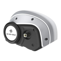
The CMT03P is a mid-motor drive unit designed for electric bicycles. It features a modular design for easy installation and maintenance, and a half-package design that allows for customer customization. The unit incorporates double clutches and is controlled by torque with a built-in controller. It offers a large starting torque, which is beneficial for climbing, and boasts high efficiency, low power consumption, and a long cruising range.
The motor's internal aluminum shell is die-cast with an electrophoresis coating in matt black. The outer plastic shell is sprayed with matt black and silver paint. The unit has a protection grade of IP65, indicating it is dust-tight and protected against low-pressure water jets from any direction. It is designed to operate in temperatures ranging from -20°C to 55°C, at atmospheric pressures corresponding to altitudes up to 1000m, and with relative humidity of ≤90% at 25°C.
The CMT03P is available in two models: CMT03P36 and CMT03P48, differing primarily in their rated power and voltage.
| Parameter | CMT03P36 | CMT03P48 |
|---|---|---|
| Rated power | 350W@105RPM | 450W@105RPM |
| Maximum input power | 500W (T<7min); max: 640W | 650W (T<7min); max: 860W |
| Rated voltage | 36V | 48V |
| Maximum current limit | 18A | 18A |
| Maximum torque | 120Nm@25RPM | 120Nm@25RPM |
| Maximum speed | 115RPM | 115RPM |
| Maximum efficiency | ≥80% | ≥80% |
The CMT03P system includes several attachments necessary for its operation and integration into an electric bicycle.
The system utilizes a medium color TFT LCD instrument, model APT 850C, for displaying various operational parameters and user interface.
The LCD display features indicators for:
The key functions on the instrument include "Up," "On/Off," and "Down" buttons for navigation and control.
For detailed parameter settings, refer to the 850C-ENS product specification -J-202106 billion.
Model: SPL-10
The speed sensor assembly includes:
The installation diagram illustrates the placement of the speed sensor and magnet on the bicycle frame, ensuring a 3-8mm gap between the sensor and the magnet. The M5 screw is used for mounting.
| Parameter | Numerical value |
|---|---|
| Rated voltage | DC5V |
| Rated current | 5mA |
| Pulse/cycle | One |
| Installation distance | 3-10mm |
| Working temperature | -30~70°C |
| Waterproof grade | IPX7 |
| Authentication | CE ROHS |
The dental tray is a circular component with a central spline for motor attachment and an outer ring for the chain.
Model: 42T unilateral chain cover
The cranks are black, elongated components designed to attach to the motor's central shaft.
Model: TS1-170AA
Note: The left and right cranks have different thread directions. The left crank is marked with "L," and the right crank is marked with "R."
The system includes various fasteners and connection plates:
The schematic diagram illustrates the interconnections between the external speed sensor, front light, display, rear light, battery, and controller. It details the wiring for each component, including positive, negative, ground, signal, and communication lines (RX/TX).
This diagram provides a visual representation of the cable lengths and connection points for all components, including the battery, external speed sensor, front light, display, and rear light, to the central motor unit. It specifies the connector types (e.g., JL-F-Z309AM 13 core female, JL-F-L611AG 6 core thread male) and cable lengths (e.g., 130mm for display, 140mm for external speed sensor).
Refer to the 2.2.3 Product Installation Diagram for specific installation requirements and positioning of the speed sensor and magnetic steel.
| Serial Num | Fault Phenomenon | Possible Causes of Failure | Debugging |
|---|---|---|---|
| One | The motor cannot be mounted on the frame. | Welding deformation of frame connecting plate. | Reduce welding deformation of frame. |
| Plug-in is not connected properly. | Check all plug-ins and connect. | ||
| Two | Meter no display | Use non-standard instruments. | Use our standard instrument. |
| The battery runs out. | Charge as required. | ||
| Three | Meter kilometers are not displayed. | The external speed sensor plug-in is not connected properly. | Check plug-in and connect. |
| Magnetic steel is not installed in place. | Check the position of magnetic steel and install it. | ||
| Four | Meter kilometer display is abnormal. | Unreasonable magnetic steel position distance. | Adjust the position distance of magnetic steel. |
| There is strong environmental interference. | Change the environment. | ||
| Five | The front/rear lights are off. | The light control module is not installed. | Install the light control module. |
| Plug-in is not connected properly. | Check all plug-ins and connect. | ||
| The rated voltage of front/rear lamps does not match. | Replace the front/rear lights with the correct voltage. | ||
| Six | No response when the brake is cut off. | Plug-in is not connected properly. | Check all plug-ins and connect. |
Note: When the motor operates without external force, it is normal for the crank to follow.
The system provides error codes and corresponding LED flashing patterns to diagnose issues.
| NO | Error Code | Wrong Definition | LED Flashing | Describe |
|---|---|---|---|---|
| 1 | 0x00 | Normal | Flash once per second | -- |
| 2 | 0x10 | Overtension | Flash once | Restorability |
| 3 | 0x11 | Undervoltage | Flash twice | Restorability |
| 4 | 0x12 | Motor speed feedback failure (such as motor stalling) | Flash 4 times | Restorability |
| 5 | 0x13 | Overtemperature | Flash 9 times | Restorability |
| 6 | 0x14 | Voltage fault | Flash 10 times | Beyond retrieve |
| 7 | 0x15 | Abnormal output | Flash 11 times | Beyond retrieve |
| 8 | 0x16 | MCU fault | Flash 12 times | Beyond retrieve |
| 9 | 0x17 | Flying car protection | Flash 13 times | Beyond retrieve |
| 10 | 0x18 | Pedal sensor failure | Flash 14 times | Beyond retrieve |
| 11 | 0x19 | Speed sensor failure | Flash 15 times | Beyond retrieve |
| 12 | 0x30 | Communication failure | The controller can't communicate with the instrument, and the instrument sends a fault code. | |
| 13 | 0x21 | Overflowing | Flash 3 times | Restorability |
| MOS tube failure | Flash 6 times | Beyond retrieve | ||
| 14 | 0x22 | Turn the voltage too high | Flash 8 times | Restorability |
| 15 | 0x23 | Phase line fault | Flash 7 times | Beyond retrieve |
| 16 | 0x24 | Hall fault | Flash 5 times | Restorability |
| 17 | 0x25 | Brake failure | Restorability |
Note:
The CMT03P package includes the following items: