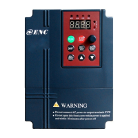
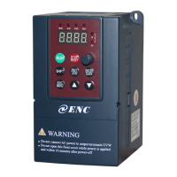
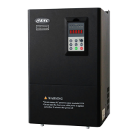
EasyManua.ls Logo

SHENZHEN ENCOM ELECTRIC TECHNOLOGIES CO. EDS1000 series User Manual

SHENZHEN ENCOM ELECTRIC TECHNOLOGIES CO. EDS1000 series
199 pages
To Next Page IconTo Next Page
Page #1 background imageLoading...
Page #1 background image
ISO9001:2000 Quality Management System Authentication
CE Authentication
EDS1000 series
0.4-75KW
Universal inverter
Ver. 3.0
SERVICE MANUAL
SHENZHEN ENCOM ELECTRIC TECHNOLOGIES CO.,LTD.

Table of Contents

Questions and Answers:

SHENZHEN ENCOM ELECTRIC TECHNOLOGIES CO. EDS1000 series Specifications

General IconGeneral
ModelEDS1000 series
Protection LevelIP20
Cooling MethodForced air cooling
Input Frequency50/60Hz
Output Voltage0~Rated Input Voltage
Control ModeV/F control
Overload Capacity150% rated current 60s; 180% rated current 10s
Braking UnitBuilt-in or external (optional)
CommunicationRS485
Ambient Temperature-10°C ~ +40°C
Storage Temperature-20℃~+60℃
Altitude≤1000m (derating required above 1000m)

Summary

SERVICE MANUAL

Foreword

Safety Information and Use Notice Points

Safety Precautions

Covers essential safety warnings and precautions for inverter operation and installation.

Use Range

Defines the applicable scope and environments for the inverter's operation.

Use Notice Points

Highlights important operational guidelines and considerations for optimal performance.

Scrap Notice Points

Provides instructions for the proper disposal of scrap inverters and their components.

Type and Specification of the Inverter

Incoming Inverter Inspect

Details checks required upon receiving the inverter to ensure it's undamaged and complete.

Series Type Explanation

Lists various inverter models in the series with their specifications and ratings.

Appearance and Parts Name Explanation

Identifies and labels the external components and parts of the inverter.

Product Technic Index and Spec

Details the technical specifications, performance indices, and operational characteristics.

Installation and Wiring

Installation Ambient

Specifies environmental conditions and requirements for safe and proper inverter installation.

Wiring Notice Points

Highlights critical safety guidelines and best practices for inverter wiring connections.

Main Loop Terminal Wiring

Details the connection procedures for the primary power and motor terminals.

Control Loop Collocation and Wiring

Explains the wiring and setup for the control circuits and terminals.

Run and Operation Explanation for Inverter

Run of Inverter

Describes the different modes and channels for controlling inverter start, stop, and run actions.

Operation and Use of Key Board

Explains the layout and functions of the inverter's control panel keys and display.

Inverter Electrification

Outlines the procedure for the initial power-up and check of the inverter system.

Function Parameter Schedule Graph

Symbol Description

Defines symbols used in parameter tables to indicate parameter status and modifiability.

F0 – Basic Run Function Parameter Group

Details parameters related to fundamental inverter running modes and frequency settings.

F1 – Start-up, Stop, Brake Function Parameter Group

Covers parameters for controlling the inverter's start-up, stopping, and braking behaviors.

F2 – Auxiliary Run Function Parameter Group

Describes parameters for auxiliary functions that enhance inverter operation and control.

F9 – Protection Correlative Function Parameter Group

Lists parameters for various protection functions to ensure safe and reliable operation.

Detailed Function Description

Basic Run Function Parameter Group: F0

Provides detailed explanations for F0 parameters controlling basic inverter run functions.

Start-up, Stop, Braking Function Parameter Group: F1

Explains F1 parameters related to the inverter's start-up, stop, and braking operations.

Auxiliary Run Function Parameter Group: F2

Details the F2 parameters that offer auxiliary functions for inverter operation.

Closed-loop Run Control Parameter Group: F3

Covers F3 parameters essential for implementing closed-loop control systems.

Simple PLC Run Function Parameter Group: F4

Describes F4 parameters for configuring the inverter's internal PLC for sequential operations.

Terminal Correlative Function Parameter Group: F5

Explains F5 parameters that define the behavior of the inverter's input and output terminals.

Troubleshooting

Failure and Countermeasure

Lists common failure codes, their possible causes, and recommended countermeasures.

Failure Record Lookup

Explains how to access and interpret stored failure codes and associated parameters.

Failure Reset

Provides procedures for resetting the inverter after a failure condition has been resolved.

Maintenance

Routine Maintenance

Details regular inspection procedures to ensure optimal inverter performance and longevity.

Inspection and Replacement of Damageable Parts

Guides on identifying and replacing components that may wear out over time.

Repair Guarantee

Outlines the terms and conditions for inverter repair services and warranty coverage.

Storage

Provides guidelines for storing the inverter to maintain its condition during periods of non-use.

Fitting Parts

Communication Subassembly

Details the communication modules and accessories for connecting the inverter.

Communication Cable

Specifies the types and lengths of communication cables used for connecting devices.

Examples

Common Speed Regulation Running

Illustrates a basic setup for controlling motor speed using keypad and basic wiring.

Terminal Control Running

Demonstrates how to control the motor using external signals via terminal connections.

Multi-step Speed Control Running

Shows how to configure multiple speed steps using terminal inputs for varied operation.

Closed-loop Control System

Explains the setup for a closed-loop system using feedback signals for precise control.

Consecutive Action Running

Demonstrates how to link multiple inverters for sequential or coordinated operation.

Application to Constant Pressure Water Supply

Provides details on using the inverter for constant pressure water supply systems.

Appendix 1 EDS1100 Drawing machine Inverter Manual

Drawing machine schematic diagram

Illustrates the mechanical setup of the drawing machine with host and wire retracting mechanisms.

Working Theory

Explains the operational principles behind maintaining constant tension and synchronizing line movement.

Drawing machine tension control

Details the specific control mode for tension management within the drawing machine application.

EDS1100 Series inverter model No. and specification

Lists model numbers and key specifications for EDS1100 inverters used in drawing machines.

Serial Port RS485 Communication Protocol

Summarization

Provides an overview of the RS485/RS232 communication interfaces and their applications.

RTU Communication Mode

Details the RTU communication mode, including data frame formats and transport protocols.

Data communication address allocation

Explains the addressing scheme for function codes and parameters in Modbus communication.

Communication error processing

Describes how communication errors are detected, reported, and handled by the inverter.

Appendix 2 The manual of middle frequency inverter

Symbol description

Defines symbols used in parameter tables to indicate parameter status and modifiability.

Function parameter schedule graph

Presents a comprehensive list of function codes, their settings, factory defaults, and modification status.

Appendix 3 Modbus communication protocol

Summarization

Provides an overview of the RS485/RS232 communication interfaces and their applications.

RTU Communication Mode

Details the RTU communication mode, including data frame formats and transport protocols.

Data communication address allocation

Explains the addressing scheme for function codes and parameters in Modbus communication.

Communication error processing

Describes how communication errors are detected, reported, and handled by the inverter.

Appendix 4 Braking resistance

Braking Resistance

Details the configuration and selection of external braking resistance for inverter applications.

Related product manuals