Mag Lock
+
-
For more info visit our web site: www.sherlotronics.com
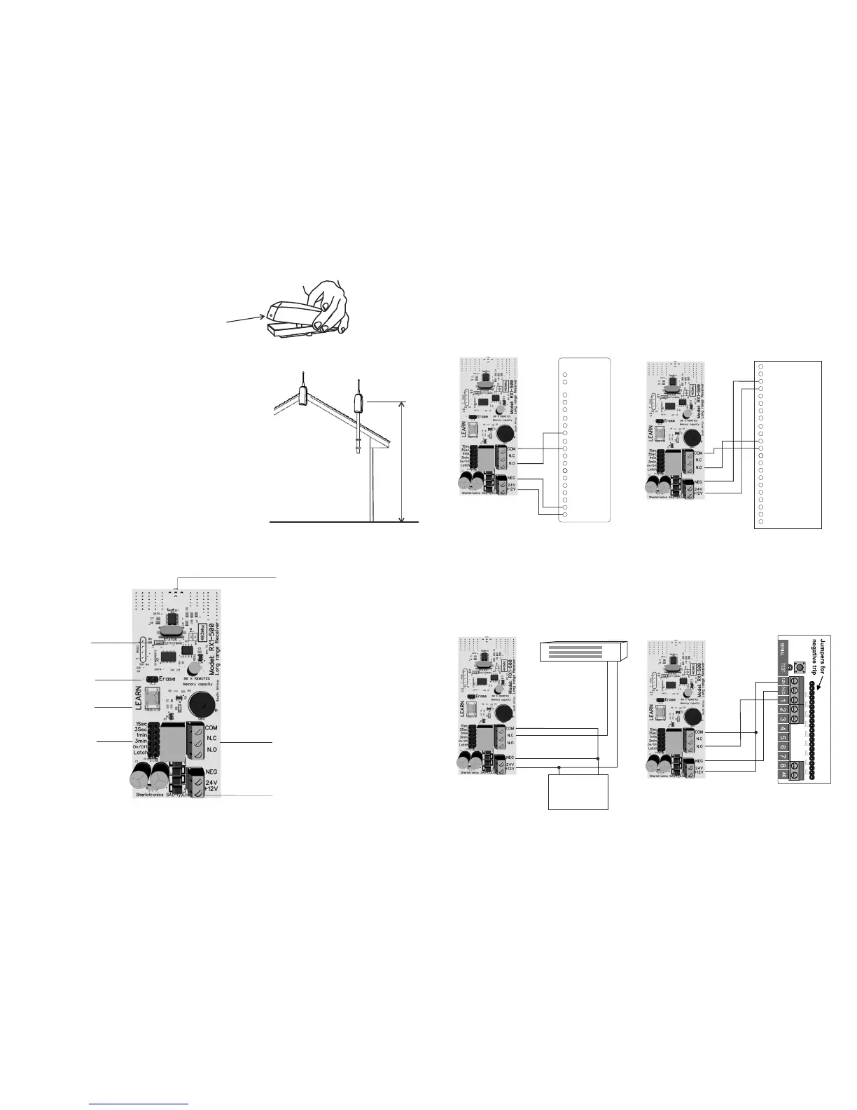
Opening the unit
Wiring diagram
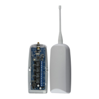
The plastic housing is splash proof, and may be mounted externally if
required. The unit should be mounted vertically for best performance.
Ensure that you do not mount the unit close to electric fence cables or
energizers, as these products produce extreme levels of interference
and may reduce the performance of the product. If mounting indoors
try and centralise the unit, and keep it at least 3 metres away from
armed response company’s alarm radio transmitters.
We recommend the unit to be mounted more than 3 metres above the
floor height just above the trap door. For large properties that require
exceptional range, mount the unit externally.
Always conduct a signal range test before you hand over the product
to the client, ensuring that the system works reliably. You may need to
move the unit if you encounter dead spots. In rare cases you may
need to install a booster repeater unit for coverage around large multi
levelled sites.
Remove the Aerial and make sure the screw on the bottom side is removed.
Carefully lift the lid up from the back end and unclip the top.
Screw hole
Mounting advice
A
B
3m
For more info visit our web site: www.sherlotronics.com
Relay time
jumpers
Terminal blocks
Status
LED
LEARN
switch
Relay
output
Aerial
Typical gate motor wiring Typical alarm panel wiring
D5
Typical mag lock Typical panic to radio transmitter
Safe Common
Aux 12V Out
Trg
Ped
Com
FRX
Aux
Status
Com
Motor
Motor
12V -
12V +
Aux IO
Lck/Stp
Close
Open
Light
Light
+
-
12V DC
Power- supply
YEL
GRN
Z1
BLK
AUX -
RED
AC
AC
AUX +
BELL+
BELL-
COM
Z2
COM
Z3
COM
Z4
COM
Z5
Z6
Z7
Z8
Positive trip
Panic
ERASE
switch
 Loading...