..
-..
Assembly Notes:
Reassembling
the
Pump
(1)
Use
Repair
Kh
82C-041
to
repair
the
displacement
asterisk, for exsmple,
(210*),
show
the
parts includ-
pump. Reference numbers in parentheses with an
ed
in the
kit.
Use
all
the
new parts even
if
the old
ones still
look
good for
the
best
results.
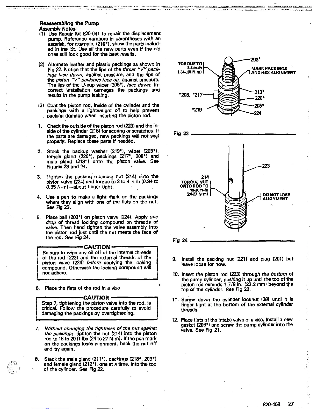
(2)
Alternate leather and plastic packings as shown in
Fig
22.
Notice
that the lips of
the
throat
"Vpack-
ings face down,
against
pressure, and the lips of
the piston "r'packings face
up,
against pressure.
The
lips
of
the U-cup wiper
(205").
face
dawn.
In-
corm installation damages
the
packings and
results
in
the pump leaking.
13)
Cost
the
piston rod, inside of the cylinder and the
packings with a lightweight oil to help prevent
,
packing damage when inserting the piston
rod.
1.
Check the outside of the piston rod
(223)
and
the
in-
side of the cylinder
(216)
for scoring or scratches.
If
the
parts
are damaged, new packings will not segl
property. Replace these parts
if
needM.
2.
Stack the backup washer
(219").
wiper
(205*),
female gland
(2209,
packings
(217",
208')
and
male gland
(213")
onto
the
piston. valve.
See
Figures
23
and
24.
3.
lighten the packing retaining nut
(214)
onto
the
piston valve
(224)
and torque to
3
to
4
in-lb
(0.34
to
0.35
Nm)-about finger tight.
4.
Use
a
pen to make
a
light
mark
on the packings
where
they
align with one of the flats on the nut.
See fig
23.
5.
Place ball
(203')
on piston valve
(224).
Apply one
valve. Then hand tighten the valve assembly into
drop
of
thread locking compound on threads of
the piston rod just until the nut meets the face
of
the
rod. See Fig
24.
6.
Place the
flats
of
the
rod
in
a
vise.
4
critical. Follow the procedure
carefully
to avoid
damaging the packings by overtightening.
7.
Without changing ?he tightness of the
nut
ag8inst
the packings, tighten the nut
(214)
into the piston
rod
to
18
to
20
fi-lbs
(24
to
27
Nm).
If
the pen mark
and
try
again.
on the packings loses alignment, back the nut
off
8.
Stack the male gland
(2119,
packings
(218'.
209')
and female gland
(212").
one at a time, into
the
top
c,.:.
,;
,.7?
...
.
j,
.
..
,,.
. . ..
.
.,
.,.. . .
...
of the cylinder.
See
Fig
22.
.-.
MARK PACKINGS
AND
HiX
ALIGNMENT
Fig
24
9.
Install the packing nut
(221)
and plug
(201)
but
:.
10.
Insert the piston rod
(223)
through the
bottom
of
the pump cylinder, pushing
it
up until the top of the
piston rod extends
1-718
in.
(32.2
mm).
beyond the
:
top of the cylinder.
See
Fig
22.
..
leave
loose
for now.
11.
Screw down the cylinder locknut
(38)
until
it
is
threads.
finger tight
at
the bottom of the external cylinder
12.
Place flats
of
the
intake valve
in
a
visa.
Install a new
gasket
(2061)
and screw the pump cylinder into the
valve.
See
Fig
21.
:...
!,
 Loading...