..
..
1.
Stop the sprayer.at the bottom of its
stroke
to get
the crank
(E)
in its lowest position.
If
the crank
(E)
must be lowered manually, carefully rotate the
blades
of
the fan
with
a
screwdriver.
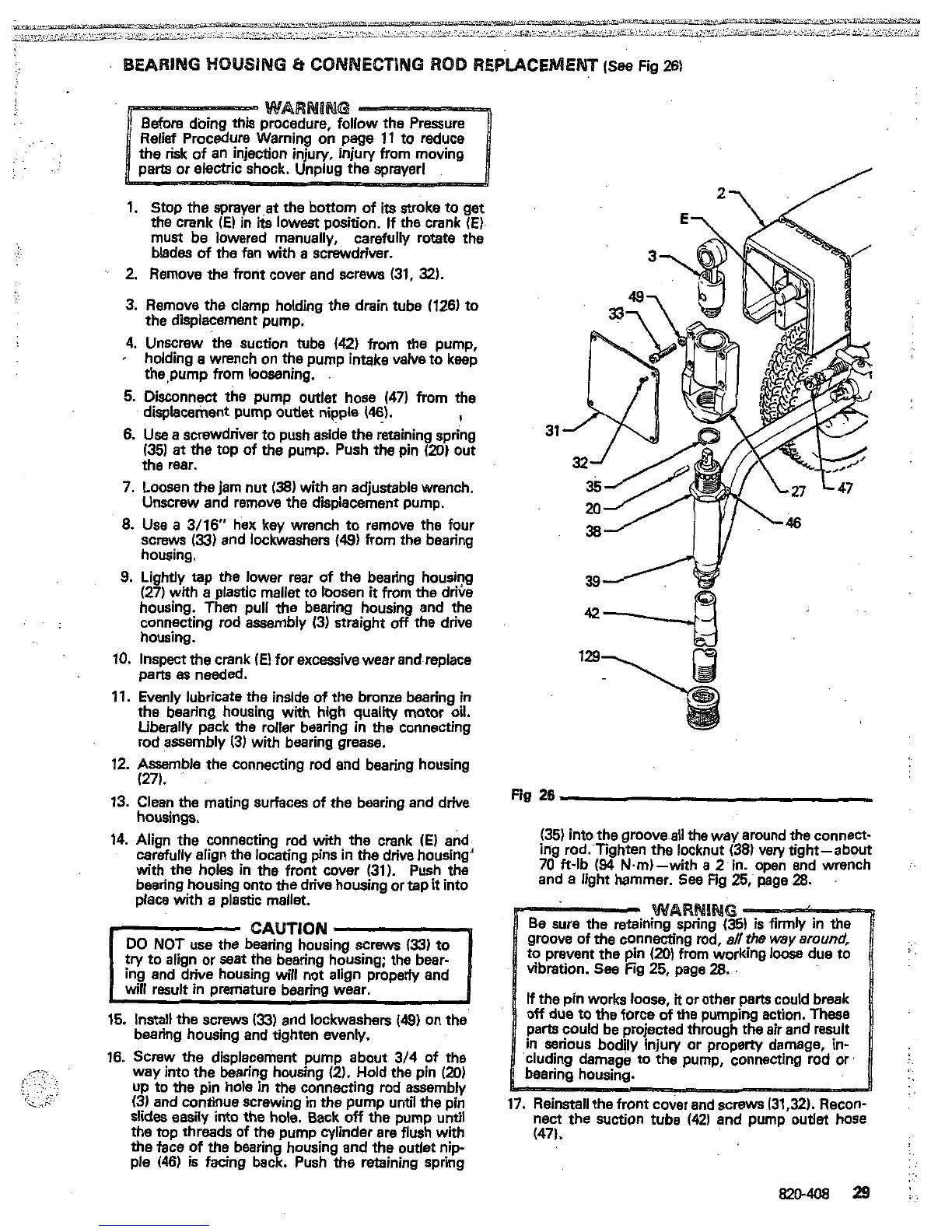
2.
Remove the front cover and screws
(31,
32).
3.
Remove the clamp holding the drain tube
(126)
to
the displacement pump.
4.
Unscrew the suction tube
(42)
from
the
pump,
holding a wrench on the pump inmke valve to keep
thepump from loosening.
5.
Disconnect the pump outlet hose
(47)
from the
displacement pump outlet nipple
(46).
I
6.
Use
a screwdriver to push aside the retaining spring
31
(35)
at
the
top of the pump. Push the pin
(20)
out
the
rear.
7.
Loosen the jam nut
(38)
with
an
adjustable wrench.
Unscrew and remove the displacement pump.
8.
Use
a
3/16
hex
key
wrench to remove the four
screws
(33)
and lockwashen
(49)
from the bearing
housing.
9.
Lightly tap the lower rear of
the
bearing housing
housing. Then pull the bearing housing and the
(27)
with a plastic mallet to loosen
it
fmm the dtik
connecting rod assembly
(3)
straight
off
the drive
housing.
10.
Inspect the crank
(E)
for excessive wear and replace
pans
es
needed.
11.
Evenly lubricate the inside
of
the bronze bearing
in
the bearing housing with high quality motor oil.
Liberally pack
the
roller bearing in
the
connecting
rod assembly
(3)
with bearing grease.
12.
Assemble the connecting rod and bearing housing
(27).
13.
Clean the mating surfaces of the bearing and drive
housings.
14.
Align the connecting rod with
the
crank
(E)
and
carefully align the locating pins in
the
drive housing'
with the holes in the front cover
(31).
Push the
bearing housing onto the drive housing or tap
it
into
place with
a
plastic mellet.
CAUTION
15.
Install
the screws
(33)
and lockwashen
(49)
on the
bearing housing and tighten evenly.
16.
Screw the displacement pump about
3/4
of
the
way into the bearing housing
(2).
Hold the pin
(20)
(3)
and continue screwing
in
the pump until the pin
up to
the
pin hole
in
the connecting rod assembly
slides easily into the hole. Back
off
the pump until
the top threads of the pump cylinder are flush with
the face
of
the
bearing housing
and
the outlet nip-
ple
(46)
is facing back. Push the retaining spring
Fig
26
(351
into the groove
all
the way around
the
connect-
70
ff-lb
(94
Nm)-with
a
2'in. open end wrench
ing rod:Tighten the locknut
(38)
very tight-about
and a light hammer.
See
Fig
25,'
page
28.
jury
or property damage,
in-
cted
through the
air
and result
the pump, connecting rod or
17.
Reinstall the front cover and screws
(31,321.
Recon-
nect
the
suction tube
(42)
and pump
outlet
hose
(471.
 Loading...