Do you have a question about the Sherwood Scientific 420 and is the answer not in the manual?
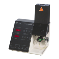
Describes the Sherwood Scientific Model 420 & 425 dual channel low temperature Flame Photometers.
Specifies the intended use of the unit by knowledgeable persons in safe laboratory practices.
Details the electrical supply, fuel, air, and waste container requirements for the instrument.
Outlines the optimal environmental and physical conditions for instrument installation.
Refers to the Operator's Manual for detailed specifications of the instrument.
Specifies the minimum warm-up time required for the flame to achieve stated performance.
Details the operating and transportation temperature and humidity ranges for the instrument.
Explains the function of front panel controls like Set, Blank, Single/Dual, Peak/Ref./Cont.
Describes front panel indicators such as Readout, CAL, Element Selection, Single, Dual, Peak.
Details rear panel connectors, including data outputs, RS232, external device, power, gas, air, and air regulator.
Lists routine maintenance procedures such as daily, weekly, monthly, and six-monthly tasks.
Describes the electrical and electronic circuits and lists the fitted Printed Circuit Boards (PCBs).
Details the Signal Sensing, Flame Sensing, Ignition Timing, and Fuel Solenoid Control functions on the main PCB.
Provides step-by-step instructions for removing and replacing the main printed circuit board (PCB).
Details the procedure for replacing the solenoid valve coils, including wire connections.
Outlines the steps for cutting tie wraps, removing tubing, and fitting new restrictors.
Provides instructions for removing the gas pipe and screws to replace the gas pressure regulator.
Details steps for removing sleeving, de-soldering wires, and replacing the air pressure switch.
Provides instructions for disconnecting plugs, ribbon cables, and screws to replace the ignitor unit.
Outlines steps for removing chimney parts, screws, and tie wraps to replace the flame sensor.
Details removing connectors, leads, and screws to replace photocells for different elements.
Provides instructions for removing and replacing filters for K, Li, Ca, and Na elements.
Explains how to program new filter factors into the instrument using button sequences.
Lists the information required when ordering spare parts, such as serial number and catalogue number.
Lists spare parts for the General Arrangement (upto s/n 20410), including photocell assembly, chimney, nebuliser.
Illustrated exploded view of the General Assembly for models from serial number 20411 onwards.
Lists spare parts for the Front Panel Assembly, including ignitor unit and main PCB assembly.
Lists spare parts for the Main Chassis Assembly, including ignition electrode, burner, and mixing chamber.
Lists spare parts for the Gas Chassis Assembly, including air pressure gauge, solenoid valves, and restrictors.
Illustrated exploded view of the Gas Chassis Assembly for models from serial number 23160 onwards.
Lists spare parts for regulators, including propane and butane regulators for various cylinder sizes.
Illustrated exploded view of the Rear Mounted Components.
A diagram illustrating the piping connections for fuel, air, and mixing chamber assembly.
Shows the wiring connections for the instrument, including PCB, solenoids, igniter, and flame sensor, with updates for later models.
| Brand | Sherwood Scientific |
|---|---|
| Model | 420 |
| Category | Measuring Instruments |
| Language | English |