The Sherwood Scuba Oasis & Blizzard Second Stages Service Guide provides comprehensive instructions for the maintenance and repair of these scuba regulators. The document is intended for experienced scuba equipment repair technicians who have received specific training from Sherwood Scuba.
Function Description:
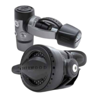
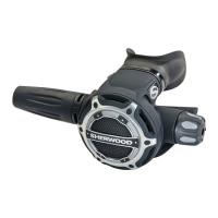
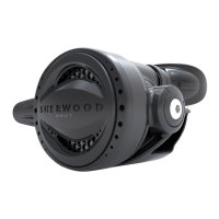
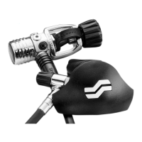
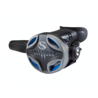
The Oasis and Blizzard second stages are critical components of a scuba regulator system, responsible for delivering breathing gas to the diver at ambient pressure. They are designed to provide smooth and easy inhalation, ensuring optimal performance under typical recreational diving conditions. These second stages are also compatible with Enriched Air Nitrox (EAN) gas mixtures with an oxygen component not exceeding 40%.
Important Technical Specifications:
- Intermediate Pressure Range: The regulator should maintain an intermediate pressure between 145 +/- 10 psi (approximately 10 bar).
- Initial Opening Effort (O.E.): Measured using a Magnehelic gauge, the initial opening effort should be between 1.4 - 1.6 inches of water for both Oasis Pro and Blizzard Pro models.
- Inhalation Test: Inhalation effort should not exceed 2.0 inches of water at opening and less than 5.0 inches of water at 15 SCFM.
- Torque Specifications:
- Hose's swivel nut onto valve body threaded end: 40 in/lb.
- Retaining nut: 28 in/lb.
- Hose's male end to 1st stage: 40 in/lb.
- EAN Compatibility: Designed for use with EAN gas with an oxygen component not exceeding 40%.
Usage Features:
- Venturi Switch: Allows for adjustment of airflow to prevent free flow at the surface and optimize breathing performance underwater.
- Purge Function: Enables the diver to clear water from the second stage.
- Moisture Retention Vanes (Oasis Pro): The Oasis Pro model includes SHV5071 vanes designed to help retain moisture in the breathing gas, enhancing diver comfort.
- Blue Exhaust Valve (Blizzard Pro): The Blizzard Pro model features a blue exhaust valve (PN# SHV7078).
Maintenance Features:
The service guide outlines a detailed annual inspection and standard service overhaul procedure.
Annual Inspection:
- Visual Inspection: Check first and second stages for damage, deterioration, and mouthpiece integrity.
- Hose Inspection: Retract hose protectors and inspect hoses for blisters, deep cuts, or separation at fittings.
- Exhaust Valve Inspection: Use a soft probe to lift and inspect the exhaust valve for cuts, tears, or contamination. Perform a suction test to check for leakage.
- First Stage Filter Inspection: Check for contamination, which may indicate the need for a standard overhaul and inspection of air cylinders.
- Intermediate Pressure Check: Install a gauge and check intermediate pressure at 500 psi and 3000 psi. Pressure should not exceed 155 psi.
- Purge Function Test: Verify a strong surge of air when purging.
- Leakage Test: Submerge the regulator and inspect for bubbles.
- Inhalation Test: Perform an inhalation test using a test bench or a subjective breathing test to ensure smooth and easy inhalation.
Standard Service Overhaul (Recommended every two years or after 300 dives):
- Disassembly: Detailed steps for disassembling the second stage, including removing the hose, mouthpiece, purge cover, Venturi switch, poppet nut, demand lever, valve body, and orifice.
- Cleaning:
- Thermoplastic, Silicone Rubber, Anodized Aluminum Parts: Soak in warm water with liquid dish detergent, scrub with a soft nylon brush, rinse with fresh water, and blow dry with compressed air. Avoid ultrasonic cleaning or vinegar solutions for these parts.
- Chrome-plated Brass and Stainless Steel Parts: Use a commercial-grade Ultrasonic Cleaner with LFW (Lawrence Factor Wash) diluted at a 1:4 LFW/Water ratio. Heated ultrasonic cleaners accelerate the process. Monitor parts for chrome peeling. Alternatively, household vinegar and warm water with a brush can be used, but may not reach deeper areas. Rinse thoroughly with fresh water and blow dry.
- Hoses: Clean metallic fittings by dipping them in cleaning solution, avoiding the inner conduit. Flush the interior with fresh water and dry with compressed air.
- Inspection:
- Sealing Surfaces: Inspect all o-ring contact surfaces for contamination, scratches, and blemishes.
- Seating Surfaces: Inspect first and second stage orifices for nicks, deep scratches, and blemishes.
- Diaphragm and Exhaust Valve: Stretch slightly against light to check for cuts, deformities, or integrity issues.
- General Components: Thoroughly inspect all components for physical integrity.
- Replacement of Consumables: The service kit (9950-PK) includes recommended replacement parts such as the plastic tie wrap (SHV7026), poppet nut (9000-47), orifice/hose swivel o-rings (970010), Venturi switch o-ring (970015), and LP seat (SHV7030).
- Lubrication: Use Tribolube 71 or Christo-Lube MCG-111. Apply a light coating for general o-rings and an ample coating for dynamic o-rings or those exposed to considerable motion/environmental conditions.
- Reassembly: Step-by-step instructions for reassembling the second stage, including installing the exhaust valve, exhaust tee cover, poppet guide, spring bushing, spring, valve end, lock nut, LP seat, orifice, valve flange, o-rings, Venturi switch, C-clip, diaphragm, diaphragm retainer, accent ring, and purge cover.
- Adjustments and Calibration:
- Orifice Pre-setting: Rotate the orifice 6 turns clockwise while depressing the demand lever.
- Calibration: Connect to an intermediate pressure source (145 +/- 10 psi) and use an in-line adjuster (20-500-200) to correct air leaks by rotating the orifice. Always depress the purge button during rotation.
- Demand Lever Height Adjustment: Access the poppet nut (17) through the Venturi switch's access point and rotate it clockwise to increase demand lever height or counterclockwise to decrease it.
- Final Checks: Cycle/purge the regulator 30+ times, measure initial opening effort, re-install hose assembly and mouthpiece, and submerge the second stage in water to check for leaks.
- Orifice Driver (20-675-200)
- O-ring pick set, soft brass (G9440-22)
- In-Line Adjustment Tool (20-500-200)
- 5-piece set Picks/Flat Screw Drivers (11-090-500)
- Blizzard Pro Nut Driver/Poppet Tool (20-612-200)
- Emphasizes the importance of reading the entire manual, referring to the illustrated parts list, using only genuine Sherwood parts, and working in a clean, properly equipped area.
- Highlights the distinction between dynamic and static o-rings and their lubrication requirements.
- Stresses the importance of using proper tools and torque wrenches to avoid damage or catastrophic failure.
- Provides specific warnings regarding hydrocarbon contamination when servicing for EAN use and the risks of adjusting opening effort below recommended values.