EasyManua.ls Logo

Shimano SG-7R46 - Service Manual

Shimano SG-7R46
12 pages
Print Icon
To Next Page IconTo Next Page
Loading...
SERVICE MANUAL
vol.1
SG-7R46
SHIMANO NEXUS 7-SPEED HUB
t
Question and Answer IconNeed help?

Do you have a question about the Shimano SG-7R46 and is the answer not in the manual?

Summary

Disassembly of the Inter-7 Hub

Tools and Initial Setup for Disassembly

Lists necessary tools and the initial step of securing the hub axle in a vice for disassembly.

Removing Left Hand Cone and Dust Cap

Instructions for removing the left hand cone and dust cap from the hub axle.

Removing Ball Retainer and Hub Shell

Details the removal of ball retainer I and the hub shell from the hub assembly.

Removing Internal Gear Components

Covers the removal of stop springs, carrier units, and gear units from the hub.

Removing Final Internal Assembly Parts

Focuses on the removal of ball retainer M from the driver unit.

Assembly of the Inter-7 Hub

Initial Setup and Ball Retainer M Installation

Securing the hub axle in a vice and placing ball retainer M onto the driver unit.

Engaging Driver Unit and Planet Pinion

Connecting planet pinion teeth in carrier unit 1 with driver unit teeth, requiring careful turning.

Installing Sun Gear and Ring Gear Units

Engaging sun gear units and placing ring gear unit 2 onto carrier unit 1.

Installing Carrier, Ring Gear, and Stop Spring

Engaging carrier components and ring gear unit 2, and inserting the stop spring.

Final Assembly Steps and Adjustments

Installing internal assembly, ball retainer I, and adjusting the left hand cone.

Installing Right Hand Dust Cap

Attaching the right hand dust cap to the hub shell and checking for smooth rotation.

Overview

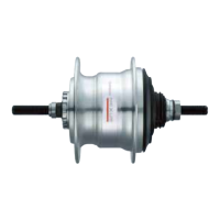
The Shimano Nexus SG-7R46 is a 7-speed internal gear hub designed for bicycles, offering a reliable and low-maintenance shifting solution. This service manual, volume 1, provides detailed instructions for the disassembly and assembly of the hub, along with a comprehensive spare parts list.

Function Description:

The SG-7R46 hub integrates a 7-speed planetary gear system within its shell, providing a wide range of gears suitable for various riding conditions without the need for an external derailleur. This internal mechanism protects the gears from dirt, impacts, and weather, contributing to its durability and consistent performance. The hub is designed to work with a Hi-Power Roller Brake (BR-IM41-R Inter-M Brake), ensuring effective stopping power. The internal assembly consists of several key components, including carrier units, sun gears, ring gears, and ball retainers, all working in concert to provide smooth gear changes. The driver unit connects to the bicycle's chain, transmitting power to the internal gears, which then drive the hub shell and the wheel. The design emphasizes a sealed system to minimize the ingress of contaminants, thus extending the life of the internal components.

Usage Features:

The internal gear hub offers several advantages for the rider. Its enclosed design means less exposure to the elements, resulting in reduced wear and tear compared to external derailleur systems. This translates to fewer adjustments and a more consistent shifting experience over time. The 7-speed range provides sufficient gearing for commuting, touring, and general recreational cycling, allowing riders to tackle both inclines and flats with ease. Shifting can be performed while stationary, which is particularly useful in urban environments with frequent stops and starts. The hub's robust construction makes it a suitable choice for daily use, offering a dependable and hassle-free cycling experience. The compatibility with a roller brake system further enhances its utility, providing reliable braking performance in various weather conditions.

Maintenance Features:

The SG-7R46 hub is designed for relatively straightforward maintenance, primarily involving disassembly, cleaning, lubrication, and reassembly. The service manual outlines a step-by-step process for these tasks.

Disassembly:

  1. Preparation: The first step involves securing the hub axle in a vice using its bevelled surfaces on the sprocket side. It's crucial to avoid damaging the axle threads during this process.
  2. Left Hand Cone Removal: The lock nut for the left hand cone and the left hand cone with dust cap are removed. Care must be taken not to damage the sections of the lock nut when using a spanner.
  3. Ball Retainer I Removal: Ball retainer I is carefully removed from the hub shell.
  4. Right Hand Dust Cap Removal: The right hand dust cap is removed using a screwdriver.
  5. Hub Shell Removal: The hub shell is then removed, exposing the internal assembly.
  6. Stop Spring and Carrier Guide 2 Removal: The stop spring for carrier guide 2 is removed using pliers. It's recommended to cover the internal assembly with a cloth to prevent the spring from flying off.
  7. Ring Gear Unit 2, Carrier Unit 2, and Carrier Guide 2 Removal: These components are removed simultaneously while turning ring gear unit 2 slightly to the left and right. After their collective removal, carrier unit 2 and carrier guide 2 are separated from ring gear unit 2.
  8. Sun Gear Unit 2 & 3 Removal: Sun gear unit 2 & 3 are removed by turning them slightly to the left and right. The manual warns against applying undue force to prevent damage to internal pawls.
  9. Carrier Unit 1 Removal: Carrier unit 1 is then removed.
  10. Ball Retainer M Removal: Finally, ball retainer M is removed from the driver unit, with a caution to avoid bending it. This completes the disassembly process.

Assembly:

  1. Preparation: Similar to disassembly, the hub axle is secured in a vice.
  2. Ball Retainer M Placement: Ball retainer M is placed onto the driver unit, ensuring correct orientation. A liberal coating of internal hub grease (Shimano part no. Y-041 20800) is applied, and care is taken not to bend the retainer.
  3. Driver Unit and Carrier Unit 1 Engagement: The teeth of the planet pinion in carrier unit 1 are engaged with the teeth of the driver unit. The driver unit is pressed in while turning it slightly left and right. A liberal coating of internal hub grease is applied to the planet pinions (3 places) in carrier unit 1.
  4. Sun Gear Unit 2 & 3 Engagement: The teeth of sun gear unit 2 & 3 are engaged with the teeth of the planet pinion in carrier unit 1. This is done by turning sun gear unit 2 & 3 slightly left and right and then pressing them into carrier unit 1. A liberal coating of internal hub grease is applied to the teeth of sun gear unit 2 & 3. The smooth ring section of the gear should be at the top, and the manual warns against applying undue force to prevent pawl damage.
  5. Ring Gear Unit 2 Placement: Ring gear unit 2 is placed onto carrier unit 1, ensuring the part with the teeth is at the top. A liberal coating of internal hub grease is applied to the teeth of ring gear unit 2.
  6. Carrier Unit 2, Carrier Guide 2, and Ring Gear Unit 2 Engagement: The teeth of the planet pinion in carrier unit 2, carrier guides 2, and the teeth of ring gear unit 2 are engaged while turning carrier unit 2 slightly left and right, then pressing into ring gear unit 2. A liberal coating of internal hub grease is applied to the planet pinion (3 places) in carrier unit 2. It's important to check that the groove in the stop ring for carrier guide 2 is visible from the edge of carrier unit 2 when pushed down.
  7. Stop Spring Insertion: While pushing down carrier guide 2, the stop spring is inserted into the hub axle groove at the surface of carrier guide 2, ensuring it is securely inserted.
  8. Internal Assembly Installation: The internal assembly is installed into the hub shell by turning the hub shell slightly right and left so that seal spring R of the hub shell sits in the right hand dust cap of the internal assembly. A liberal coating of internal hub grease is applied to the grease groove of the hub shell. A check is performed by turning the hub shell counterclockwise to ensure smooth rotation.
  9. Ball Retainer I Placement: Ball retainer I is placed onto the hub shell, ensuring correct orientation and applying a liberal coating of internal hub grease.
  10. Left Hand Cone Adjustment: The left hand cone with dust cap is screwed on and adjusted until the hub shell turns smoothly without any play. Once adjusted, the left hand cone with dust cap is secured with the lock nut for the left hand cone, taking care not to damage the lock nut sections.
  11. Hub Axle Securing: The hub axle is again held in a vice.
  12. Right Hand Dust Cap Installation: The right hand dust cap is installed, with a liberal application of grease. After installation, the hub shell is turned clockwise to check for smooth rotation. If it doesn't turn smoothly, the right hand dust cap should be re-installed.

This detailed process ensures that the hub is correctly assembled and lubricated, maintaining its optimal performance and extending its lifespan. The use of specific Shimano grease (Y-041 20800) is highlighted throughout the assembly steps, emphasizing the importance of proper lubrication for the internal mechanisms. The manual also includes a comprehensive spare parts list with Shimano code numbers and descriptions for easy identification and ordering of replacement components.

Shimano SG-7R46 Specifications

General IconGeneral
Model NumberSG-7R46
SeriesNexus
CategoryIndustrial Equipment
Speed7-speed
Gear Ratio Total244%
Gear Change Support MechanismYes
Brake TypeRoller Brake
MaterialAluminum
TypeInternal Gear Hub
Spoke Hole36H

Related product manuals