EasyManua.ls Logo

Shop fox W1812 User Manual

Shop fox W1812
56 pages
To Next Page IconTo Next Page
Page #1 background imageLoading...
Page #1 background image
OWNER'S MANUAL
Phone: (360) 734-3482 • Online Technical Support: tech-support@shopfox.biz
COPYRIGHT © MARCH, 2009 BY WOODSTOCK INTERNATIONAL, INC. REVISED NOVEMBER, 2011 (KN)
WARNING: NO PORTION OF THIS MANUAL MAY BE REPRODUCED IN ANY SHAPE OR FORM WITHOUT
THE WRITTEN APPROVAL OF WOODSTOCK INTERNATIONAL, INC.
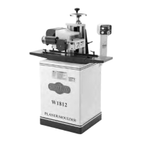
MODEL W1812
VARIABLE SPEED PLANER/
MOULDER WITH STAND
(FOR MODELS MANUFACTURED SINCE 01/12)
#11399CR  Printed in Taiwan
177335
Question and Answer IconNeed help?

Do you have a question about the Shop fox W1812 and is the answer not in the manual?

Shop fox W1812 Specifications

General IconGeneral
Motor3 HP
Planing Thickness6 inches
Cutter Head Speed5000 RPM
Max. Planing Depth1/8 inch
Voltage240V
Dust Port Size4 inches
Planing Width15 inches
Feed Rate26 FPM

Summary

INTRODUCTION

Woodstock Technical Support

Contact information for technical assistance and warranty claims.

Machine Controls and Features

Identification and description of the machine's main operational controls and features.

MACHINE SPECIFICATIONS

Dimensions and Shipping

Physical dimensions, weight, and shipping information for the machine.

Electrical and Motor Specs

Details on power requirements, switch type, cord specs, and motor technical data.

Cutting Capacities and Knife Information

Maximum material dimensions and details on knives and cutterhead.

Table, Construction, and Features

Information on table dimensions, construction materials, and overall machine features.

SAFETY

Standard Machinery Safety Instructions

General safety guidelines for operating machinery.

Safe Operation Practices

Rules for safe operation, including operator authorization and securing the workpiece.

Planer/Moulder Specific Safety

Safety precautions specific to planer and moulder operations.

ELECTRICAL

Circuit Requirements

Specifies the necessary electrical circuit for the machine.

Grounding and Extension Cords

Guidelines for proper grounding and the use of extension cords.

SETUP

Unpacking and Inventory Check

Instructions for unboxing and checking all included components.

Machine Placement

Guidance on positioning the machine considering floor load and clearances.

Lifting, Moving, and Mounting

Procedures for safely moving and securing the machine to a surface.

ASSEMBLY

Belt and Stand Assembly

Steps for assembling the drive belt and connecting the stand components.

Headstock, Motor, and Guard Installation

Instructions for installing the headstock, motor pulley, and belt guard.

Control Panel and Rail Installation

Steps for mounting the control panel and installing guide rails.

Dust Collection Setup

Instructions for installing the dust hood and connecting a dust collection system.

TEST RUN

Pre-Operation Checks and Procedure

Steps to verify machine function and safety before initial operation.

OPERATIONS

General Operation and Safety Switch

Overview of operations and how to secure the machine with the power switch.

Installing Planing Knives

Detailed steps for safely installing the planing knives.

Installing Moulding Knives

Procedure for installing moulding knives, ensuring proper clearance.

Feed Roller Adjustment

How to set feed roller height and spring tension for optimal performance.

Workpiece Inspection and Preparation

Guidelines for inspecting and preparing workpieces before machining.

Planing Best Practices

Do's and don'ts for safe and effective planing operations.

Planing Operation Guide

Step-by-step instructions for performing planing operations.

Moulding Best Practices

Do's and don'ts for safe and effective moulding operations.

Moulding Support and Knife Positioning

Techniques for supporting workpieces and positioning knives for moulding.

Workpiece Sizing and Guide Rails

How to size workpieces and use guide rails for moulding.

Moulding Tall Workpieces

Specific guidance for securely supporting tall workpieces during moulding.

Moulding Operation Guide

Step-by-step instructions for performing moulding operations.

ACCESSORIES

Moulding Knives

Catalog of available moulding knives for the machine.

Dust Collectors and Roller Stands

Information on compatible dust collection systems and roller stands.

MAINTENANCE

General Maintenance and Cleaning

Routine checks, cleaning procedures, and feed motor maintenance.

Table Care and Lubrication

Methods for maintaining the table and lubricating key machine components.

SERVICE

Feed Motor Brush Replacement

Procedure for replacing worn feed motor brushes.

Feed Roller Alignment

Steps to align feed rollers with the machine table for smooth feeding.

Drive Chain Adjustment

How to adjust the drive chain tension to prevent slack and slippage.

Gib Adjustment

Procedure for adjusting the headstock gib to remove play in the ways.

ELECTRICAL SAFETY

General Electrical Safety

Important safety warnings and guidelines for electrical work.

WIRING DIAGRAM

Machine Wiring Diagram

Visual representation of the machine's electrical connections.

Electrical Component Locations

Identifies the physical locations of key electrical components on the machine.

TROUBLESHOOTING

Motor Start and Operation Issues

Solutions for problems related to the motor not starting or running.

Vibration, Noise, Stalling, and Slowing Issues

Troubleshooting steps for vibration, noise, stalling, or slowing machine operation.

Workpiece Feed and Surface Finish Issues

Fixes for snipe, workpiece stalling, chipping, fuzzy grain, and surface marks.

PARTS

Headstock Component Diagram

Exploded view and labeling of headstock parts.

Headstock Parts List

Detailed list of all parts for the headstock assembly.

MAIN MOTOR & CABINET

Motor and Cabinet Components

Diagram and parts list for the main motor and cabinet.

FEED MOTOR & CONTROLS

Feed Motor and Control Components

Diagram of the feed motor and its associated controls.

Feed Motor and Controls Parts List

Detailed list of parts for the feed motor and control systems.

LABEL PLACEMENT

Safety and Identification Label Locations

Diagram showing the placement of all safety and identification labels on the machine.

WARRANTY

Limited Two-Year Warranty

Terms and conditions of the manufacturer's warranty.

Related product manuals