ITEM DESCRIPTION PART NO.
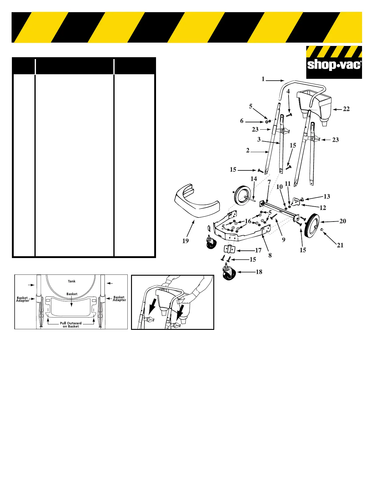
1 Handle (16”) 20855-03
2 Handle upright 20856-01
3 Handle brace 20857-01
4
1
/
4
- 20 x 1
1
/
4
" Hex head machine 09074-99
screw (Black)
5
1
/
4
" External tooth lockwasher 23010-99
6
1
/
4
- 20 Hex nut (Black) 13035-99
7 Rear dolly frame (16”) 20837-00
8 Main dolly frame (16”) 20836-00
9
5
/
16
-18 x 2
1
/
2
" Hex head bolt 09073-99
10
5
/
16
" - Split lockwasher 02005-99
11
5
/
16
- 18 Hex nut 13003-99
12 Tank retainer bracket 20853-00
13 Threaded knob 23301-00
14 Axle (16”) 24407-00
15
1
/
4
- 20 x
5
/
8
" Hex head
machine screw 09028-99
16
1
/
4
- 20 Hex nut 13001-99
17 Caster socket 75400-01
18 Caster 67729-00
19 Bumper (16”) 87811-01
20 10” Wheel (25.4cm) Gray 24207-00
21 Cap nut 43002-99
22 Accessory basket (16”) 74429-02
23 Basket adapter 74429-50
Dolly Assembly Instructions
Tools required:
(2)
1
/
2
inch open end wrenches, (2)
7
/
16
inch open end wrenches, or a
socket set and a hammer.
1. Insert 2
1
/
2
inch long bolt through center hole in rear frame, attach
split lockwasher, nut and tighten securely.
2. Attach handle brace to back of rear frame with
5
/
8
inch long machine
screws, lockwashers, and nuts. (Finger tighten only.)
3. Position main frame inside rear frame. Attach (2)
5
/
8
inch long
machine screws, lockwashers and nuts in both sides. Tighten
securely.
4. Attach handle uprights, inside main frame (make sure buttons at top
face inward) using
5
/
8
inch long machine screws, lockwashers and
nuts. (Finger tighten only.) Align holes at top of handle braces with
holes in handle uprights. Attach with 1
1
/
4
inch long machine screws,
lockwashers and nuts. (Tighten securely.)
5. Go back and tighten machine screws at bottom of uprights and
braces.
6. Attach caster sockets (open end down) to front of main frame using
5
/
8
inch long machine screws, lockwashers and nuts. Insert casters
into sockets.
7. Slide basket adapters on handle.
8. See Fig. 1 for correct installation of adapters.
9. Attach handle onto uprights by pushing down and holding buttons in
on uprights.
10. Place tank retaining bracket through slot and bolt in rear frame and
screw on knob.
11. Slide bumper down over main dolly frame until it bottoms out.
12. Place axle upright on a hard surface and hammer on (1) cap nut.
Place (1) wheel on axle and slide down to cap nut. Slide axle
through rear of frame and slide on other wheel. Before assembling
cap nut on other end of axle, be certain dolly is assembled correct-
ly. (You may place tank on dolly and tighten knob of retaining brack-
et to be sure of correct assembly.)
13. After ensuring dolly is assembled correctly remove tank and place
dolly on side with installed cap nut on hard surface and hammer sec-
ond cap nut on axle.
14. Place accessory basket on adapters and pull out on outer rim of bas-
ket and snap into place. (Fig 2)