E N
Nome file:
7540028EN - CUSTOMER MANUAL SF15_200 TOP EN.docx Rev. 1 12/06/2017
20-28
7 User instructions.
7.1 Foreseen use and adjustments.
We suggest to start the filter twice a day for 4 or 5 hours.
Regularly check if backwash is necessary, please see Tab. 2.
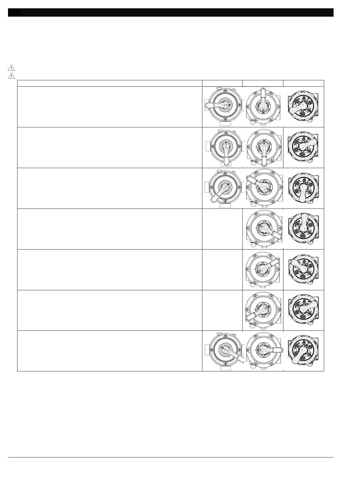
Use and functioning of the multifunctional valve.
7.1.1
Always switch off the pump when operating on the multifunctional valve’s lever.
It is recommended to install valves in the inlet and outlet pipelines (hydraulic parts).
FILTRATION.
The water in the pool enters the multifunctional valve
the PUMP connector (Fig. 33, # 1), travels through the
media (from top to bottom), exits from the POOL
(Fig. 33, # 3) and returns clean to the pool.
.
The water in the pool enters the multifunctional valve
the PUMP connector (Fig. 33, # 1), travels through the
media
(from bottom to top) stirring it, exits from the
WASTE connector (Fig. 33
, # 4) getting rid of the impurities
.
The water in the pool enters the multifunctional valve
the PUMP connector (Fig. 33, # 1), travels through the
media
(from top to bottom) compacting it, exits from the
WASTE connector (Fig. 33
, # 4) getting rid of the impurities
VALVE CLOSED (only on 6-way multifunctional valve).
The water in the pool does not cross the filter. The PUMP
connector (Fig. 33, # 1) is closed.
-
WASTE (only on 6-way multifunctional valve).
The water in the pool enters the multifunctional valve
the PUMP connector (Fig. 33
, # 1), exits straight from the
WASTE connector (Fig. 33
, # 4) without going through the
filter media.
-
CIRCULATION (only on 6-way multifunctional valve).
The water in the pool enters the multifunctional valve
the PUMP connector (Fig. 33
, # 1) and exits from the
POOL connector (Fig. 33, # 3) going back to the
without crossing the filter media.
-
WINTER.
Rest position of the multifunctional valve
internal components of the multifunctional valve itself
Position suitable for storage.
Tab. 3
 Loading...