Do you have a question about the SHS HT7 Series and is the answer not in the manual?
General precautions for handling, installation, and use of automation components.
Details of the power supply and motor connectors (J1A and J1B).
Information on the FIELDBUS connector (J3) and its signals.
Description of J2A (Left) and J2B (Right) input/output connectors.
Configuration settings using DIP switches and RJ45 connector details.
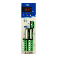
Explanation of the meaning of RUN, ERR, and STS status LEDs.
Overview of protection features and error messages displayed by the drive.
Guide to accessing and setting drive parameters using the display and buttons.
Physical dimensions and mounting specifications for the drive.
Important safety and installation guidelines for the drive.
Specifications and notes for connecting an AC power supply to the drive.
Illustrates the electrical connections for AC power and motor wiring.
Specifications and notes for connecting a DC power supply to the drive.
Illustrates the electrical connections for DC power and motor wiring.
Details of digital and analog input/output features and voltage levels.
Schematics and descriptions for isolated and non-isolated digital inputs.
Schematics and descriptions for isolated and non-isolated digital outputs.
Wiring diagrams for various types of encoder inputs (differential, single-ended).
Schematics for analog input and output signals, and connection notes.
Indicates that the drive can be operated in PROFINET mode.
Instructions for configuring the PROFINET master using a device master file.
Explanation of data format and structure for PROFINET communication.
Details the data structure for communication from the HT7 drive to the PROFINET master.
Defines the control bits (ZSW) for PROFINET communication between master and slave.
Details the status bits (STW) transmitted from the drive to the PROFINET master.
Illustrates the timing for positioning commands using ZSW bits.
Step-by-step sequence for executing relative positioning commands.
Step-by-step sequence for executing absolute positioning commands.
Step-by-step sequence for executing Jog CW and Jog CCW commands.
Instructions and logic for homing the motor using sensors.
Configures the motor rotation start frequency.
Configures the motor rotation working frequency.
Sets the ramp inclination for motion commands.
Sets the motor resolution for step-based movements.
Configures current reduction mode when the motor is stopped.
Sets the time for electric current reduction after the motor stops.
Sets the motor current value.
Indicates relative positioning relative to the current motor position.
Indicates absolute positioning relative to the home position.
Associates an entered value with the motor's home position.
Reads or writes the current motor position register.
Reads the motor rotation frequency.
Reads the motor destination quote.
Defines inputs and levels for executing a START command.
Defines inputs and levels for executing a STOP command (AND logic).
Defines inputs and levels for executing a STOP command (OR logic).
Defines inputs and levels for executing a HOME command.
Defines inputs/levels for zeroing motor position value.
Input/level definition for axis zeroing using a zero switch.
Input/level definition for limit switch to stop motor motion.
Masks positioning for enabling the zerofly trigger.
Indicates positioning in the same direction for the zerofly trigger condition.
Enables or disables low noise mode for the drive.
Defines the type of protection active (short circuit, thermal, etc.).
Manages active protection states and resets.
Displays the current software version of the drive.
Displays the drive's DC power supply voltage.
Displays the drive's current temperature.
Reads or writes the encoder position in steps.
Sets the drive's operating mode for encoder feedback.
Sets the number of pulses per revolution for the encoder.
Sets encoder steps to detect positioning errors.
Defines the frequency for searching the encoder index.
Selects the mode for searching the encoder index.
Defines special versions: Dedicated Software (Dzz) or Modified Hardware (Szz).
Details available options for drive configuration.
Lists available Fieldbus communication protocols (WS, MB, CO, PB, PN, EC, EI, MT).
Specifies drive size based on voltage and current ratings.
Code mapping for various options like encoder type, inputs, and outputs.