Do you have a question about the Shuangri Electron SR258 and is the answer not in the manual?
Safety precautions during installation and commissioning of the controller.
Overview of the manual's content, scope, and intended audience for proper operation.
Manufacturer's disclaimer regarding damages from improper installation, operation, or maintenance.
Notes on potential errors and disclaimers about manual accuracy.
Explanation of symbols used for safety and operation notes.
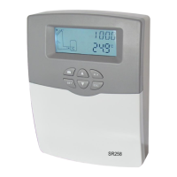
Details on controller buttons and Human-Machine Interface.
Comprehensive list of technical specifications for the controller.
List of components included in the product package.
Step-by-step guide for physically installing the controller on a wall.
Instructions on how to route and connect electrical wiring.
Detailed explanation of terminal connections for inputs and outputs.
Specific guidance for connecting high-efficiency pumps.
Details on various output ports like R1, R2, R3, and HR and their functions.
Table mapping sensors (T1-T5) and relays (R1-R3, HR) to their functions.
Visual representation of the controller's menu hierarchy.
Instructions on how to navigate and operate the controller's menus.
How to view current values and parameters on the controller.
Guide to setting the system clock and time.
Configuration for timed heating cycles using the electrical backup heater, including default settings and intelligent mode.
How to configure the DHW circulation pump based on time or temperature, including control modes.
How to set and manage passwords for accessing controller settings.
Configuration for tank heating functions, including AT control, speed control, and maximum temperature protection.
Overview of collector functions like emergency shutdown, cooling, minimum temperature, and antifreeze.
Explanation of different control modes for Pump R1, including ON/OFF, PULS, PSOL, PHEA, and 0-10V.
Overview of system cooling, tank cooling, and heat transferring functions, with details on settings.
Overview of auxiliary functions like timer, thermostat, and beeper warning, with setup procedures.
How to manually adjust relay outputs for service work, including function setup.
Function to protect pumps against blocking after standstill, with function setting details.
Function to prevent Legionella spread by activating after-heating, including monitoring and heating parameters.
Monitors flow rate to ensure normal system operation and prevent dry running, with function setting.
Allows switching temperature units between Celsius and Fahrenheit, with function setting.
Resets all parameters to factory default settings, with procedure.
Procedure for setting and changing the controller's password, with function setting.
Allows manual triggering of the backup heating function, including activation and deactivation.
Cools down the system to reduce thermal load during holidays, including activation and deactivation.
Controller retains parameters after power interruption.
Automatic screen dimming after inactivity to save power.
Guide to diagnosing common problems and their causes, including troubleshooting steps.
Wiring diagram for connecting the SR802 unit for high power electrical heater.
| Device Type | Remote Control |
|---|---|
| Model | SR258 |
| Brand | Shuangri Electron |
| Frequency | 433MHz |
| Battery Type | CR2032 |
| Operating Voltage | 3V |
| Transmission Distance | 100m (open area) |