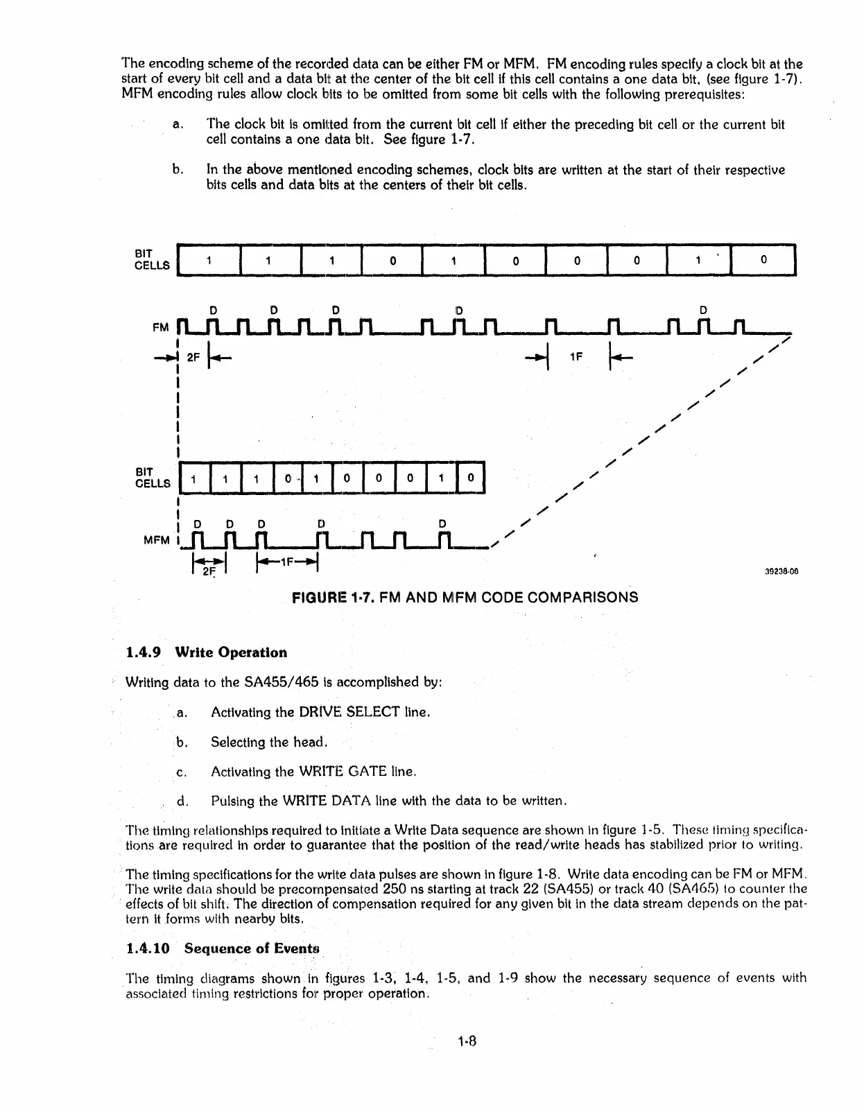
The
encoding
scheme
of
the
recorded
data
can
be either
FM
or
MFM.
FM
encoding rules specify a clock bit at
the
start of every bit cell
and
a
data
bit
at
the
center
of the bit cell
if
this cell contains a
one
data
bit. (see figure 1-7).
MFM
encoding rules allow clock bits to be omitted from
some
bit cells with the following prerequisites:
a.
The
clock bit
is
omitted from
the
current bit cell
If
either
the
preceding bit cell
or
the
current bit
cell contains a
one
data
bit.
See
figure 1-7.
b.
In
the
above
mentioned
encoding
schem,~s,
clock bits
are
written at
the
start of their respective
bits cells
and
data
bits
at
the
centers of their bit cells.
~~LLS
l
...
l~
o
~
__
o
__
..
__
o
__
...
_o
·_I
..
__
o
__
39238·06
o
DOD
0
FM
n....n.JL..n...n
I
I.
.J
1F
1_.
~",'"
~
2F r--
....,
I
",'
I
",
I
'"
I /
I
",'"
I /
,
",
~~LLS=
///
:
//
I 0 0 0
[).
.
D.
",
MFM
··IJt.JLJ1----fL.-fl-.n..-n._;
",
tvt
1--
1
F-.f
FIGURE 1·7. FM AND MFM CODE COMPARISONS
1.4.9
Write
Operation
Writing
data
to the
SA455/465
is
accomplished by:
a. Activating
the
DRIVE SELECT line.
b. Selecting
the
head.
c. Activating
the
WHITE GATE line.
d. Pulsing the WRITE DATA line with the
data
to be written.
The
timing relationships required to Initiate a Write
Dalta
sequence
are shown
In
figure 1-5. These
timinrJ
specifica-
tlonsare
required
in
order
to
guarantee
that the position of the
read/write
heads
has stabilized prior to writing.
The
timingspecifications for the write
data
pulses
are
shown
In
figure 1-8. Write data encoding can be
FM
or
MFM.
The
write data should be precornpensated
250
ns starting at track
22
(SA455) or track
40
(SA465) to counter the
effects of
bit
shifL
The
direction of compensation required for
any
given bit
In
the data stream
depends
on
the pat-
tern
It
forms
with nearby bits.
1.4.10
Sequence
of
Event~i
The
timing diagrams shown
in
figures 1-3, 1-4. 1-5.
and
1-9 show
the
necessary
sequence
of events with
.associated timing restrictions
fOli
proper
operation.
1-8
 Loading...