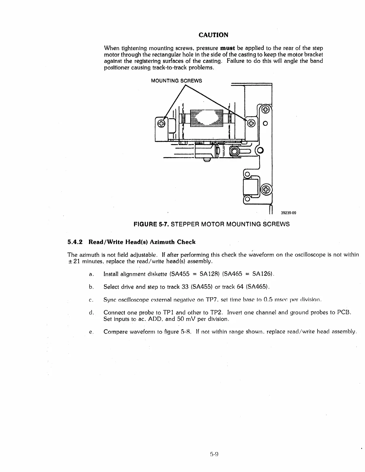
CAUTION
When
tlght~mlng
mounting screws, pressure must be applied to the rear
of
the step
motor
through the rectangular hole
In
the side
of
the casting
to
keep the
motor
bracket
against the registering surfaces
of
the casting. Failure to
do
this will angle the band
positioner
causing track-to-track problems.
MOUNTING SCREWS
39239·09
I=IGURE
5-7. STEPPIER MOTOR
MOUNTING
SCREWS
a.
Install alignment
dlsl<ette
(SA455 = SA128) (SA465 = SA126).
b.
Select drive and step to track
33
(SA455) or track
64
(SA465).
c.
Sync oscilloscope external neUi'ltlve on TP7,
set
lime bast' to 0, G m!.;(lC
pOl'
division,
d. Connect
on(~
probe to
TPl
and other to TP2, Invert one channel and ground probes to PCB.
Set inputs to ac.
ADD.
and
50
mV per division.
e,
Compare waveform to figure 5·8.
If
not within range shown. replace
read/write
head assembly.
5·9



 To Next Page