Impedance
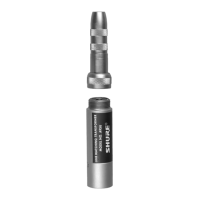
XLR Pin Connector (M): 7500Ω or 600Ω
XLR Socket Connector (F): 33,000Ω
Voltage Ratio 7500 Ω 600 Ω
Medium-impedance to
high-impedance: +6.4 dB +17.4 dB
High-impedance to
medium-impedance: –6.4 dB –17.4 dB
Driving Source Winding Being Maximum
Impedance (ohms) Driven (ohms) Level (Volts)
600 600 0.5
600 7,500 2.5
600 33,000 6.0
7,500 7,500 1.5
7,500 33,000 5.0
33,000 33,000 5.0
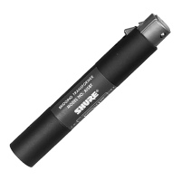
Case
Full magnetic shield, steel with gray enamel nish
Dimensions
19 mm (3/4 in.) diameter; 89 mm (3 1/2 in.) long