EasyManua.ls Logo

Shure A95U User Manual

Shure A95U
4 pages
To Next Page IconTo Next Page
Page #1 background imageLoading...
Page #1 background image
©2009 Shure Incorporated
27C1925 (Rev. 5)
Model A95U
User Guide
Printed in U.S.A.
MODEL A95U LINE MATCHING TRANSFORMER
This reversible transformer matches low- or high-impedance microphones to
high- or low-impedance inputs. The transformer permits use of very long micro-
phone cables with either low- or high-impedance microphones. However, when
connecting a high-impedance microphone, limit the cable length between the mi-
crophone and the transformer to 4.6 m (15 ft). The cable from the transformer to
the low-impedance input can be any desired length.
The transformer prevents high-frequency loss, level loss, and pickup of noise
and hum. The A95U comes furnished with a three-pin XLR connector on the
low-impedance end, with a 1/4 in. phone plug and phone jack adapter on the
high-impedance end.
Case
Full magnetic shield, steel with gray enamel finish
Dimensions
19 mm (3/4 in.) diameter; 89 mm (31/2 in.) long without adapters
LOW-IMPEDANCE SELECTION
The A95U comes factory preset with the low-impedance end intended for use
with microphones or inputs rated 75 to 300 ohms. For microphones or input rated
at 19 to 75 ohms, make the following changes.
1. Remove the low-impedance XLR plug by turning the lock screw counter-
clockwise and withdrawing the XLR plug from the case.
Question and Answer IconNeed help?

Do you have a question about the Shure A95U and is the answer not in the manual?

Shure A95U Specifications

General IconGeneral
BrandShure
ModelA95U
CategoryTransformer
LanguageEnglish

Summary

Model A95U Line Matching Transformer

Case

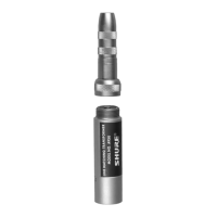
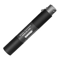
Describes the transformer's construction: full magnetic shield, steel with gray enamel finish.

Dimensions

Provides the physical size specifications of the transformer: 19 mm diameter, 89 mm long.

Low-Impedance Selection

Specifications

Frequency Response

Details the audio frequency range and flatness, specified as flat from 20 Hz to 20 kHz.

Impedance

Specifies low impedance (75-300 Ω or 19-75 Ω) and medium impedance characteristics.

DC Resistance

Lists the DC resistance values for low and high impedance settings.

Voltage Ratio

Outlines the voltage conversion ratios between low and high impedance configurations.

Maximum Recommended Input Levels

Defines the maximum safe input voltage levels for various source impedances and winding types.

Limited Warranty

Related product manuals