Accessory 28-volt DC: To convert to dc operation, this
jack is used as a power input when using the Model
A68B Battery Power Supply (Accessory). When not
using the mixer turn off the switch to conserve battery
life (pilot light does not operate when using
A68B).
Grounding
If there should be objectionable hum, connect the
metal chassis of the mixer to a good ground such as
a metal frame of a wall outlet or a water or steam pipe.
This is normally accomplished automatically through
the ground wire of the power cord.
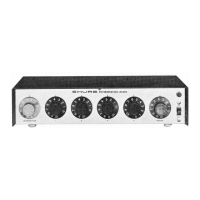
Reverberation
The red control knob (on front panel) marked RE-
VERBERATION is used to adjust the amount of rever-
beration to the desired effect.
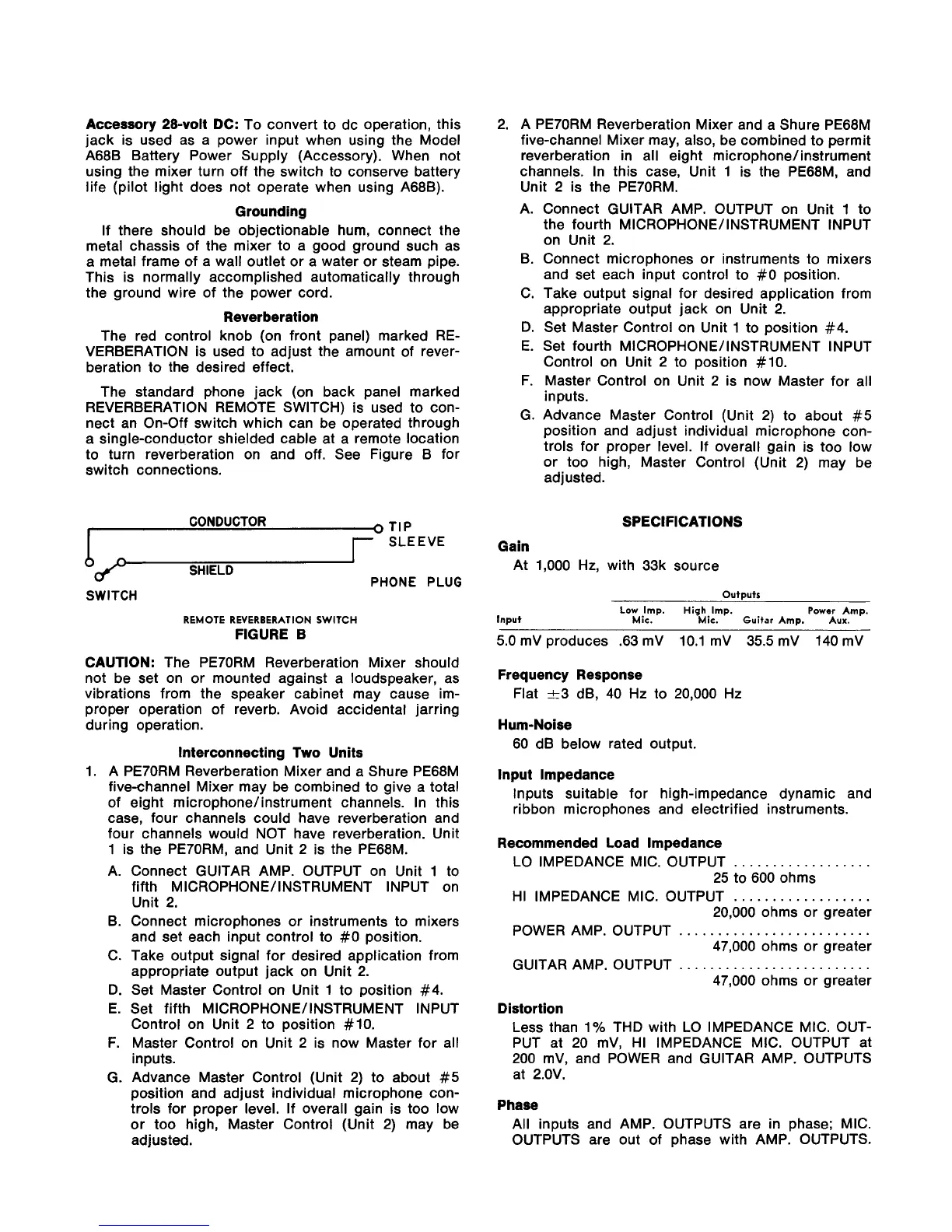
The standard phone jack (on back panel marked
REVERBERATION REMOTE SWITCH) is used to con-
nect an On-Off switch which can be operated through
a single-conductor shielded cable at a remote location
to turn reverberation on and off. See Figure B for
switch connections.
CONDUCTOR
o
TIP
r
SLEEVE
1
SHIELD
PHONE PLUG
SWITCH
REMOTE
REVERBERATION
SWITCH
FIGURE
B
CAUTION: The PE70RM Reverberation Mixer should
not be set on or mounted against a loudspeaker, as
vibrations from the speaker cabinet may cause im-
proper operation of reverb. Avoid accidental jarring
during operation.
Interconnecting Two Units
1. A
PE70RM Reverberation Mixer and a Shure PE68M
five-channel Mixer may be combined to give a total
of eight
microphone/instrument channels. In this
case, four channels could have reverberation and
four channels would NOT have reverberation. Unit
1 is the
PE70RM, and Unit 2 is the PE68M.
A. Connect GUITAR AMP. OUTPUT on Unit 1 to
fifth
MICROPHONE/INSTRUMENT INPUT on
Unit 2.
B. Connect microphones or instruments to mixers
and set each input control to
#O
position.
C. Take output signal for desired application from
appropriate output jack on Unit 2.
D. Set Master Control on Unit 1 to position #4.
E. Set fifth
MICROPHONE/INSTRUMENT INPUT
Control on Unit 2 to position
#lo.
F.
Master Control on Unit 2 is now Master for all
inputs.
G. Advance Master Control (Unit 2) to about
#5
position and adjust individual microphone con-
trols for proper level. If overall gain is too low
or too high, Master Control (Unit 2) may be
adjusted.
A
PE70RM Reverberation Mixer and a Shure PE68M
five-channel Mixer may, also, be combined to permit
reverberation in all eight
microphone/instrument
channels. In this case, Unit 1 is the PE68M, and
Unit 2 is the
PE70RM.
A. Connect GUITAR AMP. OUTPUT on Unit 1 to
the fourth
MICROPHONE/INSTRUMENT INPUT
on Unit 2.
B. Connect microphones or instruments to mixers
and set each input control to
#O
position.
C. Take output signal for desired application from
appropriate output jack on Unit 2.
D. Set Master Control on Unit 1 to position #4.
E. Set fourth
MICROPHONE/INSTRUMENT INPUT
Control on Unit 2 to position
#lo.
F.
Master Control on Unit 2 is now Master for all
inputs.
G. Advance Master Control (Unit 2) to about
#5
position and adjust individual microphone con-
trols for proper level. If overall gain is too low
or too high, Master Control (Unit 2) may be
adjusted.
SPECIFICATIONS
Gain
At 1,000 Hz, with 33k source
Low
Imp.
High
Imp.
Power
Amp.
Input
Mic.
Mic.
Guitar
Amp.
Aux.
5.0 mV produces .63 mV 10.1 mV 35.5 mV 14%
Frequency Response
Flat +3 dB, 40 Hz to 20,000 Hz
Hum-Noise
60 dB below rated output.
lnput lmpedance
Inputs suitable for high-impedance dynamic and
ribbon microphones and electrified instruments.
Recommended Load lmpedance
LO IMPEDANCE MIC. OUTPUT
..................
25 to 600 ohms
HI IMPEDANCE MIC. OUTPUT
..................
20,000 ohms or greater
POWER AMP. OUTPUT
.........................
47,000 ohms or greater
GUITAR AMP. OUTPUT
.........................
47,000 ohms or greater
Distortion
Less than 1% THD with LO IMPEDANCE MIC. OUT-
PUT at 20
mV, HI IMPEDANCE MIC. OUTPUT at
200
mV, and POWER and GUITAR AMP. OUTPUTS
at
2.OV.
Phase
All inputs and AMP. OUTPUTS are in phase; MIC.
OUTPUTS are out of phase with AMP. OUTPUTS.
 Loading...