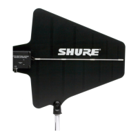
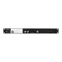
② Gain Mode LED
Indicates the current gain switch setting.
③ RF Overload LED
Indicates a strong RF signal that is overloading the antenna amplifier, which results in distortion or poor performance. Increase the distance between the antenna
and transmitter, or lower the antenna gain setting.
NOTE: RF Overload LED does not operate for passive gain settings (−6 dB or 0 dB).
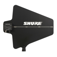
④ BNC Connector
Connect to a receiver or antenna combiner with RF inputs that supply 10–15 V DC bias.
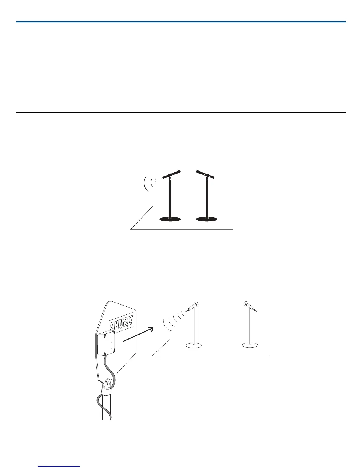
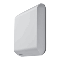
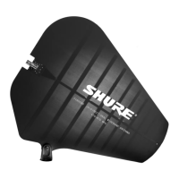
Antenna Placement
Use the following guidelines when mounting antennas:
• Antennas and receivers must be from the same band.
• Mount antennas at least one wavelength (two feet) apart.
• Position antennas so there is nothing obstructing a line of sight to the transmitter (including the audience).
• Keep antennas away from metal objects.
Important: Always perform a "walk around" test to verify coverage before using a wireless system during a speech or performance. Experiment with antenna
placement to find the optimum location. If necessary, mark "trouble spots" and ask presenters or performers to avoid those areas.
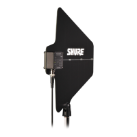
Shure IncorporatedUA874Z Active Directional Antenna
2017/11/022/4