www.sitech.se
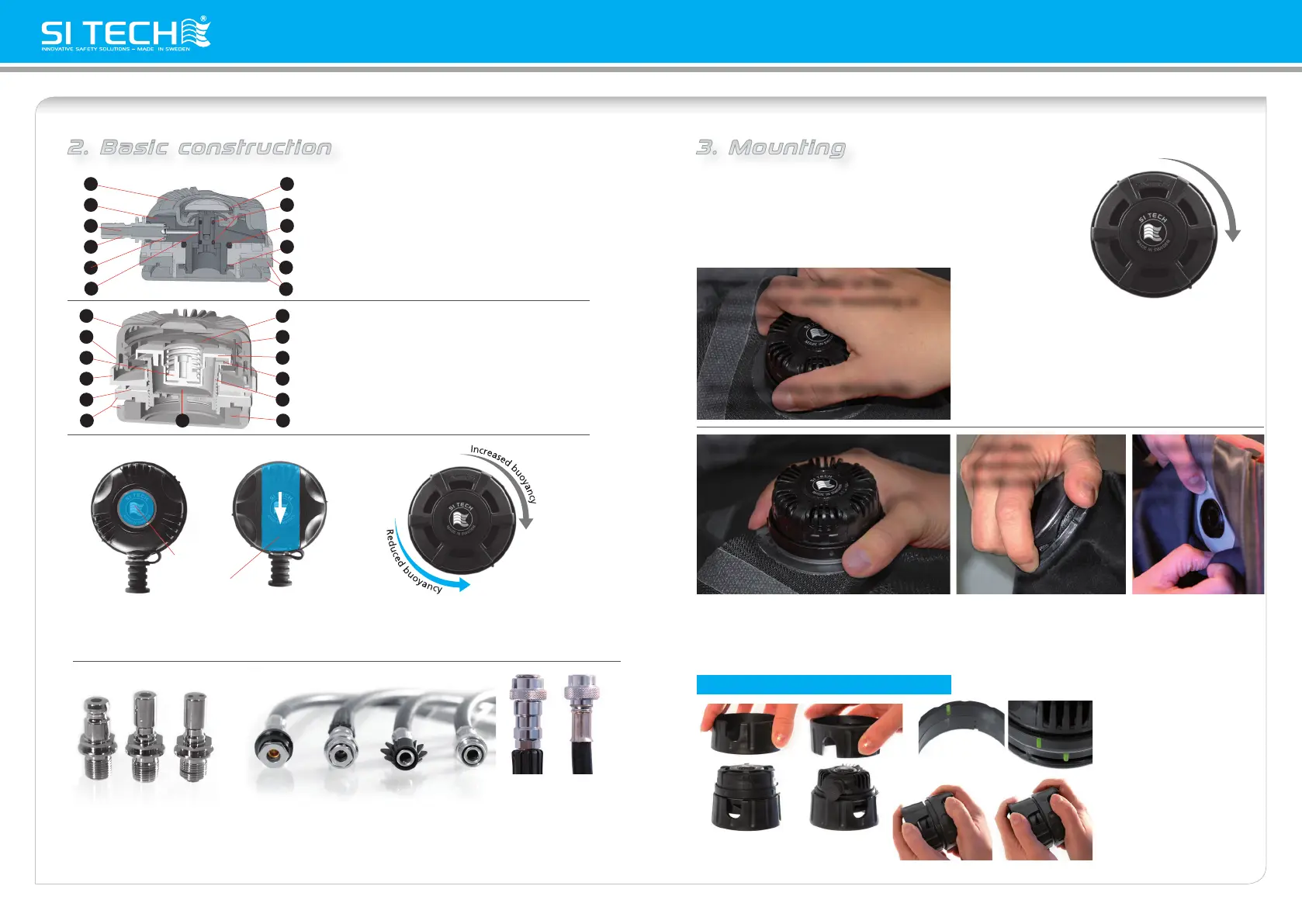
2. Basic construction 3. Mounting
(+)
• Hold the protection ring in a firm grip, turn the attachment nut on the inside of the drysuit by hand until
you feel its firmly tightened. The Anti-friction washer should always be used, positioned between the
suit and the nut. • Use the attachment tools when applying torque. Be sure that the valve is settled
correctly into the guide ridge of the Valve Port.
Do not hold the cover on the
Exhaust Valve when mounting or
detaching!
Over tightening may destroy the
valve! Please use the attachment tools.
NEVER use the cover/lid to tighten the valve. Do not
mix the Exhaust and Inflation attachment nuts when
re-fitting the valves. Note that the Exhaust Valve
attachment nut has a filter! If the valve is impossible
to detach, although using the appropriate tools
correctly, contact your dealer.
Hold the protection ring in
a firm grip!
...turn the
attachment nut
on the inside...
...Anti-friction
washer shall
always be
used...
...match the
notches on
the tools to
the barbs on
the valves.
DO NOT OVER TIGHTEN
THE VALVE!
This might cause damage to
the drysuit and/or the valve.
If you have any doubts, please
contact a qualified technician.
Usage of attachment tools!
These instructions cover drysuits equipped with SI TECH Valve Ports,
ensuring a safe and tight fitting according to standard requirement.
• Prior to detachment from the suit and prior to re-attachment into
the suit Valve Port, make sure that the Exhaust Valve cover is
adjusted clockwise to full stop (+).
Incorrect Correct
2
3
4
5
6
1 7
8
9
10
11
12
13
1. Cover/lid
2. Adjustment ring
3. Center guide
4. Protecting ring
5. Anti-friction washer
6. Attachment nut & filter lid
7. Adjustment lid
1. Cover/lid
2. House (rotating)
3. Tongue
4. Opening connector
5. O-ring
6. Stem piston
7. Push button
8. Retainer
9. Piston
10. Membrane
11. Guide sleeve
12. Filter
13. Check valve
8. O-rings
9. O-ring
10. Lock ring
11. Anti-friction washer
12. Attachment nut
Exhaust Valve
Inflation Valve
2
3
4
5
6
1 7
8
9
10
12
11
SI TECH Inflation Valves include valves operated
by push or slide button. The capacity and
function of the valves are the same.
Operated by
Push button
Operated by Slide button
SI TECH Exhaust Valves are designed to be set for
automatic buoyancy control. A ratchet function provi-
des the opportunity to fine tune the release of gas!
Cejn
Quick-On
Quick-OnInt´l
Quick-On
BasicInt´l Int´l
Variations
Connectors and Hoses
Cejn Int´l Int´l
SI TECH Inflation Valves can be delivered with either Cejn or Int´l connector (Slide Inflation Valve is only
available with Int´l). There are also the opportunity of choosing between a ”Quick-On” hose connector
or a basic version operated manually. The ”Quick-On” locks when pushed on to the male connector of
the valve. Hoses and connectors shall be inspected annually.
 Loading...