The SAS-900 is an AIS Class A / Inland transceiver designed for marine use, providing automatic identification and vessel information reporting. It allows vessels equipped with AIS to automatically and dynamically share and regularly update their position, speed, course, and other information, such as vessel identity, with similarly equipped vessels. Position data is derived from GLONASS or GPS, and communication between vessels occurs via VHF digital transmissions. This device is engineered for high performance and durability, intended to provide reliable service for many years.
Important Notices and Safety Warnings:
The manual emphasizes several critical safety warnings. The equipment must be installed according to the provided instructions, and it is strongly recommended that a trained technician performs the installation and configuration to ensure proper performance and reliability. The product must be connected to protective ground via a dedicated ground connection point, which should be bonded to protective ground using the shortest possible connection. This equipment is intended as a navigation aid and not a replacement for proper navigational judgment; information provided by the equipment should not be solely relied upon as accurate, and user decisions based on this information are at the user's own risk. The device should not be installed in flammable atmospheres, such as engine rooms or near fuel tanks, nor in direct sunlight or under a windshield where it may be subject to excessive solar heating. Users are warned against attempting to service the equipment themselves, as this could cause fire, electric shock, or malfunction and will invalidate the warranty.
General Notices:
All marine AIS transceivers, including the SAS-900, use a satellite-based location system like GLONASS or GPS. The accuracy of a GNSS position fix can vary depending on factors such as antenna positioning, the number of satellites used, and the duration of satellite information reception. The compass safe distance for this AIS transceiver is 0.5m or greater for a 0.3° deviation, and the safe operating distance from the antenna is 20cm. The product is categorized as 'protected' according to IEC 60945 definitions. Disposal of the AIS transceiver and its packaging should comply with the European WEEE Directive or applicable local regulations.
Regulatory Statements:
The manufacturer declares that this product complies with the Radio Equipment Directive (2014/53/EU) and bears the CE mark. It also complies with FCC Part 15 for Class A digital devices, designed to provide reasonable protection against harmful interference. The device must accept any interference received, and changes or modifications not expressly approved could void the user's authority to operate the equipment. For Industry Canada, the device complies with licence-exempt RSS standard(s), and operation is subject to not causing interference and accepting any interference received.
Installation and Configuration:
The SAS-900 AIS transceiver comes with a mounting bracket, power cable, 14-way data cable, 18-way data cable, GNSS antenna cable assembly, product CD, product manual, warranty card, product mounting template, quick start guide, and quick operation guide.
Installation Procedures:
- AIS Transceiver: It should be located at least 0.5m from a compass or magnetic device, with adequate space for cable routing (refer to Figure 30 for dimensions). The ambient temperature should be between -15°C and +55°C, with adequate ventilation if panel-mounted. It is recommended for 'below decks' installation, protected from weather. The transceiver can be desk-mounted using the supplied bracket or panel-mounted (requiring access behind the panel). The display should be visible from the vessel's normal operating position. A drilling and cutting template is provided.
- VHF Antenna: A suitable VHF antenna with a PL-259 (UHF) connector is required. A surge arrestor should be fitted in line with the VHF antenna connector. The antenna should be located as high as possible, with an unobstructed view, and at least 3m (10ft) away from other transmitting radio, satellite, and radar antennas. Ideally, it should be mounted directly above or below the ship’s primary VHF radiotelephone antenna, with no horizontal separation and a minimum of 2m vertical separation (refer to Figure 9). The cable should be as short as possible, using high-quality, low-loss co-axial cable, and outdoor connectors must be watertight. Cables should be installed in separate signal channels, at least 10cm (4ins) from power supply cables, avoiding sharp bends and right-angle crossings.
- GNSS Antenna: The supplied GNSS antenna comes with 10m (32.8ft) of cable. Extension cables may be needed. A one-inch 14 TPI pole mount is required. The antenna should be secured to a rigid surface, with a clear, unobstructed view of the sky, and mounted as high as possible, but not on a high mast where vessel motion could reduce accuracy. It should be at least 5m (16ft) from radar or satellite communication antennas and away from the radar beam path (refer to Figure 7).
- Data Interface Cables: Screened, multi-core cables are needed to connect ship's sensor data (DGPS, Gyro, etc.) to the AIS transceiver.
Connecting the Equipment:
The AIS transceiver has six NMEA0183 (IEC61162-1/2) data ports: three input-only ports for ship's sensor data and three bi-directional high-speed ports for display equipment (radar, ECDIS). Unused ports should be terminated with a 120 Ohm resistor across RX A and RX B signals, and COMMON signals should be grounded. Sensor ports can be configured via the 'Home' > 'System settings' > 'Interfaces' menu, including disabling the requirement for DTM (Datum) sentences from external GNSS sensors.
- Silent Mode Switch: Activated by applying 2V-30V to SILENT P (Pin 7) and SILENT N (Pin 6) of the 14-way connector.
- Alarm Connections: The transceiver provides alarm relay contacts (COM and NC) with a contact rating of 2A at 220VDC or 60W maximum.
- Power Connection: The 2-way power cable connects to a 12VDC-24VDC supply. For SOLAS vessels, connection to an emergency power source is required. A 12VDC supply needs 6.0A peak current, fused at 10.0A. A 24VDC supply needs 4.0A peak current, fused at 6.3A.
- Grounding: An M4 grounding screw and ring crimp are provided for connection to the grounding point on the rear chassis.
- NMEA2000 Network (Optional): Connects via a suitable NMEA2000 network cable. Supported PGNs are listed in the manual.
- USB Connection (Optional): An optional USB cable connects to a PC or Mac. USB drivers (on product CD) must be installed for PC. The AIS unit appears as a new COM port device, using a baud rate of 38,400. If the USB connection is removed during use, the connection must be reset by disconnecting and reapplying power to the AIS, then relaunching applications and reconnecting the USB cable.
Operation:
The AIS transceiver operates immediately when power is applied, with no On/Off switch.
- Passwords and Security: Important information is password-protected. The default password is '0000' and should be changed via 'Home' > 'System settings' > 'User Settings' > 'Password'.
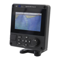
- Display and Controls: The front panel includes a display, scroll wheel (for navigation and selection), Navigation status / Screen brightness key (short press for navigation status, press and hold for brightness), Options menu key, Back / Home key (short press to cancel/previous menu, press and hold for home screen), Select key, Up/down/left/right function keys, and a speaker (for key presses, messages, alarms). A Micro SD card slot is located behind a door on the lower left.
- Menu Navigation: Menus are icon-based. Selecting an icon displays information, and 'Back / Home' exits the menu.
- Information Displayed: The display shows menu title, time (from GNSS or AIS Base Stations), time offset, speed/course (from GNSS), position (from GNSS), and various icons: RX (receiving AIS message), TX (transmitting AIS message), Filtering (target filter settings apply), Blue sign (Inland only), Navigation status, Alarms (acknowledged or unacknowledged), Messages (envelope icon with count), and Status indicators (Table 5).
- Alarms: The transceiver performs continuous self-checks. Failures trigger on-screen notifications and sounds. Alarms can be acknowledged, and a list of active alarms is available in the 'Alarms' menu. Persistent alarms require dealer/installer contact. Table 6 lists possible alarm conditions (e.g., TX Malfunction, RX Channel x malfunction, Antenna VSWR exceeds limit, External EPFS lost, No valid COG/SOG/ROT information, UTC Sync Invalid, Nav Status Incorrect, Active AIS SART, Internal/External GNSS mismatch, Heading sensor offset).
- Messages: AIS text messages and Safety Related Messages (SRMs) can be received and sent. An envelope icon indicates unread messages. The transceiver stores up to 20 messages in Inbox and Sent folders. SRMs trigger pop-up notifications; standard text messages display an icon. Class B AIS transceivers may not receive addressed SRMs or text messages.
- Long Range Messages: If connected to a long-range communication system, the transceiver can receive long-range interrogations from distant base stations. It can be configured for automatic or manual response via 'Home' > 'System settings' > 'Advanced' > 'Radio and Long range settings'.
- Chart Feature: Enabled only for non-SOLAS or Inland vessels. Displays AIS targets and own vessel position on a chart-style plot. Chart can be scrolled, zoomed, and oriented (North, Heading, Course Up). Targets can be selected for details. Options menu provides advanced features like de-cluttering and SOG vectors. The chart is an aid for information display only and not for vessel navigation.
- Help and Support: Provides contact information and relevant user manual information.
- User Settings: Allows setting display brightness, day/night colour scheme, operating units (metric/nautical), sound configuration, UTC time offset, password change, filter settings, and language.
- Vessel Identification: Requires MMSI, Ship name (max 20 chars), Callsign (max 7 chars), IMO number (if applicable), Ship type, and Internal/External GNSS antenna dimensions (refer to Figure 22).
- Internal GNSS Receiver: Configurable to GLONASS and GPS (default, best performance), GPS only, or GLONASS only.
- Voyage Related Data: Requires Destination (max 20 chars), ETA, Static draught (nearest 1/10th metre), Navigation status, and Persons on board (optional). Inland mode requires additional data (refer to Section 5).
Confirming Correct Operation:
- Check 'Own dynamic data' for correct position, course, speed, and heading.
- Verify the 'TX' icon flashes periodically.
- Check 'Target list' for other AIS-equipped vessels.
- In 'Home' > 'System settings' > 'System Information' > 'Hardware status', check supply voltage, forward power (good is 41dBm), and antenna VSWR (good is 3:1).
Communication Test:
An AIS communication test can be performed with another AIS-equipped vessel via 'Home' > 'System settings' > 'Advanced' > 'Installation & AIS SART test'. This menu also allows toggling the display of test messages from AIS SARTs.
Inland Mode:
The SAS-900 supports both standard 'high seas' (Class A) and 'Inland AIS' operations.
- Switching Modes: Select 'Home' > 'System settings' > 'Operating mode'. 'INLAND' is displayed in the menu title bar when active.
- Inland Vessel Identification Settings: Requires additional information: quality setting for speed, course, and heading data sources (high/low), vessel's ENI (8-digit number), ship and convoy type (ERI code), and length/beam to the nearest 10cm.
- Inland Vessel Voyage Settings: Requires vessel’s load status (Loaded, Unloaded, Unknown), number of blue cones or blue flag status, static draught (nearest centimetre), number of crew/passengers/shipboard personnel, and convoy dimensions (bow, stern, port, starboard extensions in metres, refer to Figure 26).
- Inland Alarm Masking: System alarms for external GNSS, Heading, or Rate of Turn sensors can be disabled in Inland mode via the 'Alarms' screen.
- Blue Sign Switch: An isolated input for a 'Blue Sign' switch (BLUE_SIGN_P and BLUE_SIGN_N) is provided. When enabled and a positive voltage is applied, Blue Sign status is displayed and transmitted in AIS position reports (refer to Figure 27). Neither Blue Sign terminal should be connected to any other point on the AIS transceiver side of any isolation barrier.
- Interface Circuits: Sensor data input ports (14-way connector) and bi-directional data ports (18-way connector) are detailed with schematics (Figures 28, 29). Input ports are logical low (A-B < -0.2V) and high (A-B > +0.2V). Bi-directional ports are isolated and can supply up to 30mA output current at 0V/3.3V.
- DGNSS Port: Intended for beacon receiver connection, with physical characteristics similar to bi-directional data ports. Can be re-configured as an additional bi-directional port to IEC61162-2 if not used for DGNSS.
- Input Data Sentence Formats: All data input via IEC61162 / NMEA 0183 sentences.
- Overall Dimensions: AIS Transceiver: 152mm (W) x 165mm (H) x 111mm (D). GNSS Antenna: 75mm diameter, 68mm height.
- Transmission Intervals: IEC61162 sentences are output in response to events or at regular intervals (Table 7).
- Interface Sentences: IEC61162 sentences accepted and output by serial data ports (Table 8).
- Unused Fields: Specific unused fields in AIR, DTM, GBS, GGA, GNS, RMC, VBW, VTG sentences are listed (Table 9).
- Proprietary Sentences: None output in normal operation.
- Priority of Sensor Ports: Automatic priority scheme for connected sensors (Position, COG+SOG, Heading, Rate of Turn). Priority order for ports is listed (Table 10).
- Compatibility Mode: For devices requiring it, the fix quality flag reports either No GNSS or GNSS. Configurable per sensor port.
- Message 24 Content: Unit Serial Number in AIS Message 24B is encoded as wwww wwyy yxxx xxxx (week, year, incrementing number).
- NMEA 2000 PGN List: Supported PGNs are listed (Table 11).
Troubleshooting:
Table 12 provides solutions for common issues like no data from chart plotter, unilluminated screen, RED 'Alarm' icon flashing (MMSI, VHF antenna, GPS fix, power supply issues), and external sensors not recognized (Compatibility Mode, Baud Rate, wiring).
Junction Box Accessory:
- What’s in the box: Junction box, self-tapping screws, 14-way extension cable, 18-way extension cable, quick start guide.
- Installation: Mount within 2m of the AIS transceiver. Connect extension cables. Remove lid with a 3mm Allen key. Route accessory cables through waterproof cable glands to terminal blocks. Use wiring diagrams (Figures 11, 13). Secure ground/screen/shield to metallic strips or appropriate terminal block connection. Termination jumpers ensure correct 120 Ohm termination to serial ports; remove if no termination is needed. Secure cables with ties. Refit lid securely.
- Connecting External Equipment: Example shown in Figure 34. Common line should connect to an available sensor port. Cable shield should be connected at one end only. Chassis connection can be via drain wire or directly to cable shield.
Technical Specifications:
- Physical: Junction box dimensions: 235mm x 69mm x 233mm (WxHxD), weight: 0.65kg. AIS Transceiver: 152mm x 165mm x 111mm (WxHxD), weight: 1.5kg.
- Environmental: Operating temperature: -15°C to +55°C. Max operating humidity: 90% at +40°C, non-condensing. Water ingress rating: IPx6, IPx7.
- Electrical: Supply voltage: 12VDC to 24VDC (min 10.8V, max 31.2V). Power consumption: < 12W. Current consumption: 0.9A typical, 6.0A peak @12VDC; 0.5A typical, 4.0A peak @24VDC.
- Display and User Interface: 800 x 480 pixel colour LCD with adjustable backlight (500cd/m² max, 75cd/m² default). Recommended viewing distance: 45cm. Keypad: Five function keys, three menu keys with adjustable backlight. Rotary control: Encoder with push function. Speaker: 600mW@750Hz 11mm x 15mm.
- Internal GNSS: 32 channels GPS and GLONASS. Time to first fix: typically 26 seconds. Frequency: L1 GPS band (1575.42MHz) and L1 GLONASS band (1597.1-1609.5MHz). Accuracy: 2.5m CEP / 5.0m SEP without differential correction; 2.0m CEP / 3.0m SEP with SBAS or RTCM DGPS correction. Antenna requirement: Active antenna (5V bias) with gain >15dB.
- TDMA Transmitter: Frequency range: 156.025MHz to 162.025MHz. Channel bandwidth: 25kHz. Output power: 1W or 12.5W (automatic selection). Data transmission rate: 9600 bits/s. Modulation mode: 25kHz GMSK.
- TDMA Receiver: Number of receivers: 2. Frequency range: 156.025MHz to 162.025MHz. Channel bandwidth: 25kHz. Sensitivity: <-107dBm for 20% PER. Modulation mode: 25kHz GMSK. Adjacent channel selectivity: 70dB. Spurious response rejection: 70dB.
- DSC Receiver: Number of receivers: 1. Frequency: 156.525MHz (Channel 70). Channel bandwidth: 25kHz. Sensitivity: -107dBm @ BER <10-2. Modulation mode: 25kHz AFSK. Adjacent channel selectivity: 70dB. Spurious response rejection: 70dB.
- RF Connections: VHF Antenna: SO-239 / UHF, 50 Ohms. GNSS Antenna: TNC female, 50 Ohms.
- WiFi: Max output power IEEE 802.11g/n: +15dBm. Max output power IEEE 802.11b: +17dBm.
- Data Interface:
- Sensor data input ports: 3 ports, IEC61162-1/-2 standard, 4800 or 38400 baud, 54K Ohms impedance.
- Bi-directional data ports (including pilot port): 3 ports, IEC61162-1/-2 standard, 4800 or 38400 baud, 54K Ohms impedance.
- Differential correction port: ITU 823-2 / RTCM SC-104 standard, 4800 or 38400 baud, 54K Ohms impedance.
- Blue Sign port: 10K Ohms impedance.
- Silent Mode port: 10K Ohms impedance.
- NMEA 2000 Port: Load equivalency number (LEN) 1.
- Power and Data Connector Information: Lists Chogori part numbers for power, 18-way data, and 14-way data connectors and their mating halves.
Installation Record:
A record should be completed and retained on board the vessel, including vessel name, flag state, IMO number, MMSI number, owner, radio call sign, type of vessel, gross registered tonnage, length (m), beam (m), AIS Transceiver serial number, installation password, radio software version number, MKD software version number, external GNSS antenna location (A, B, C, D dimensions), connected equipment type (DGPS Receiver, Gyro compass, ROT Indication, Speed log, ECDIS, Radar, Other equipment, Power supply), and attached drawings (Antenna layout, AIS arrangement, Block diagram of interconnection). A maintenance record is also provided to log modifications and software updates.