Do you have a question about the Si-tex T-760 Series and is the answer not in the manual?
Explains model naming conventions based on unit combinations.
Lists all items included in the standard package for the radar system.
Defines safety symbols (DANGER, WARNING, CAUTION) and their meanings.
Details the parts included in the packing for the display unit.
Illustrates the physical features and labels of the scanner units.
Highlights the importance of proper installation for effective radar performance.
Provides guidance on selecting the optimal position and mounting methods for the display.
Details criteria for selecting scanner installation positions and ensuring view angle.
Explains the procedure for connecting the scanner and display units via the installation cable.
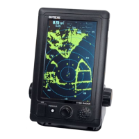
Describes the various elements visible on the radar display screen.
Identifies and explains the functions of the control panel keys and rotary knob.
Outlines the procedure for powering the radar unit on and off, including preheating.
Details the different screen modes (Normal, Graphical, Numerical) and their layouts.
Provides a summary of the functions associated with various icons on the display.
Explains how to adjust the radar's observation range using the interface.
Guides on setting the radar echo gain for optimal target detection and clarity.
Describes how to adjust the sea clutter suppression level to reduce unwanted echoes.
Explains how to use the Variable Range Marker (VRM) and Electronic Bearing Line (EBL) functions.
Details the Man Overboard function for immediate location marking and search.
Explains how to set up and use radar trails to track target movement and aid collision avoidance.
Covers the display and interpretation of Automatic Identification System (AIS) target data.
Describes how to select and configure different operational modes (Standard, Coast, Float, River).
Explains how to place and manage marks on the radar screen for referencing points.
Covers adjustments for radar echo display, including pulse length and target enhancement.
Details the process of tuning the radar for optimal performance using automatic or manual modes.
Explains settings related to target tracking, CPA/TCPA limits, and display options.
Describes how to connect and use an external monitor with the radar system.
Details the NMEA cable requirements for connecting navigation equipment.
Allows the user to select the preferred language for the system interface.
Guides on fine-tuning receiver circuits to match transmitter output for maximum sensitivity.
Explains how to align radar target bearing with ship's compass bearing.
Covers settings for connected JRC GPS receivers, including status and configuration.
Details various GPS settings like NMEA version, correction method, and fix mode.
Covers advanced adjustments for radar echo display like main bang suppression.
Explains scanner-specific settings such as pulse repetition frequency and antenna rotation.
Describes controls for touch panel calibration and buzzer settings.
Provides options for system resets, time clearing, and table updates for maintenance.
Covers system configurations like master/slave modes, ship outline, and unit settings.
Allows customization of screen appearance, including vector display and color settings.
Explains how to manage and mask system error alarms for scanners and display units.
Outlines essential cleaning and upkeep procedures for the radar equipment.
Details specific maintenance procedures for the scanner and display units.
Details methods for checking system performance, including test menus and self-tests.
Lists parts requiring periodic replacement and their service life intervals.
Provides a list of system alarms and their descriptions for troubleshooting.
Guides users on the process and necessary information for product repair.
A checklist to help diagnose and report potential radar failures.
Provides instructions on the proper disposal of the radar unit.
Information regarding hazardous substances in compliance with China RoHS standards.
Technical drawings and dimensions for the NKE-1066(NL) scanner.
Technical drawings and dimensions for the NCD-2256(ST) display unit.
Provides a general overview of the radar system's components and features.
Lists key technical specifications of the radar system, including environmental and power requirements.
Electrical diagrams showing how scanner units connect to other system components.
A summary guide for quick reference to radar operations, often for display on the unit.
A comprehensive list of all menu items and their available settings within the radar system.
Critical safety warnings regarding high voltage components within the equipment.
Safety instructions for handling individuals who have experienced an electric shock.
General guidelines for providing first aid in emergency situations.
Specific precautions to be taken by first-aiders when administering treatment.
Procedure for artificial respiration and cardiac massage when a patient has no pulse.
| Display Size | 7 inches |
|---|---|
| Display Resolution | 800 x 480 pixels |
| GPS | Yes |
| Waterproof Rating | IPX7 |
| Power Consumption | 12W |
| Display Type | TFT LCD |
| Operating Temperature | -15°C to +55°C |
| Weight | 1.2 kg |
| Power Supply | 12-24 VDC |