E7014
10
BLINKING
Lockout due to a malfunction of the inner relays. In case after a reset
procedure attempt the indication is still present, the device has to be
sent back to the manufacturer for inspection.
FIXED
Malfunction of to the local push button or of the digital input signal (for
remote operation): they are fixed on the “pressed” position during the
self-diagnosis phase. The causes could be related to the connection of
the remote signal, to the absence of RC filter, or to a malfunction of the
push button. In order to reset the alarm cut off the electrical supply to
the device for few seconds.
FIXED
Malfunction due to corruption of the inner memory of the device or to a
failure of the safety circuit. The failure could be temporary or definitive
and the causes could be related to wrong or inadequate electrical
connections of the device. In order to reset the alarm cut off the
electrical supply to the device for few seconds. In case after a reset
procedure attempt the indication is still present, the device has to be
sent back to the manufacturer for inspection.
FIXED
Malfunction due to short-circuit of the inner safety circuit relays. In order
to reset the alarm cut off the electrical supply to the device for few
seconds. In case after a reset procedure attempt the indication is still
present, the device has to be sent back to the manufacturer for
inspection.
FIXED
Malfunction due to short-circuit of the microprocessors’ pins. In order to
reset the alarm cut off the electrical supply to the device for few
seconds. In case after a reset procedure attempt the indication is still
present, the device has to be sent back to the manufacturer for
inspection.
FIXED
Malfunction due to a jump code program. The failure could be
temporary or definitive and the causes could be related to wrong or
inadequate electrical connections of the device. In order to reset the
alarm cut off the electrical supply to the device for few seconds. In case
after a reset procedure attempt the indication is still present, the device
has to be sent back to the manufacturer for inspection.
DISPLAY AND
BARGRAPH
BLINKING
Malfunction due to an excessively high ambient temperature. In these
conditions the device turn on and off continuously, showing only the
self-diagnosis initial procedure.
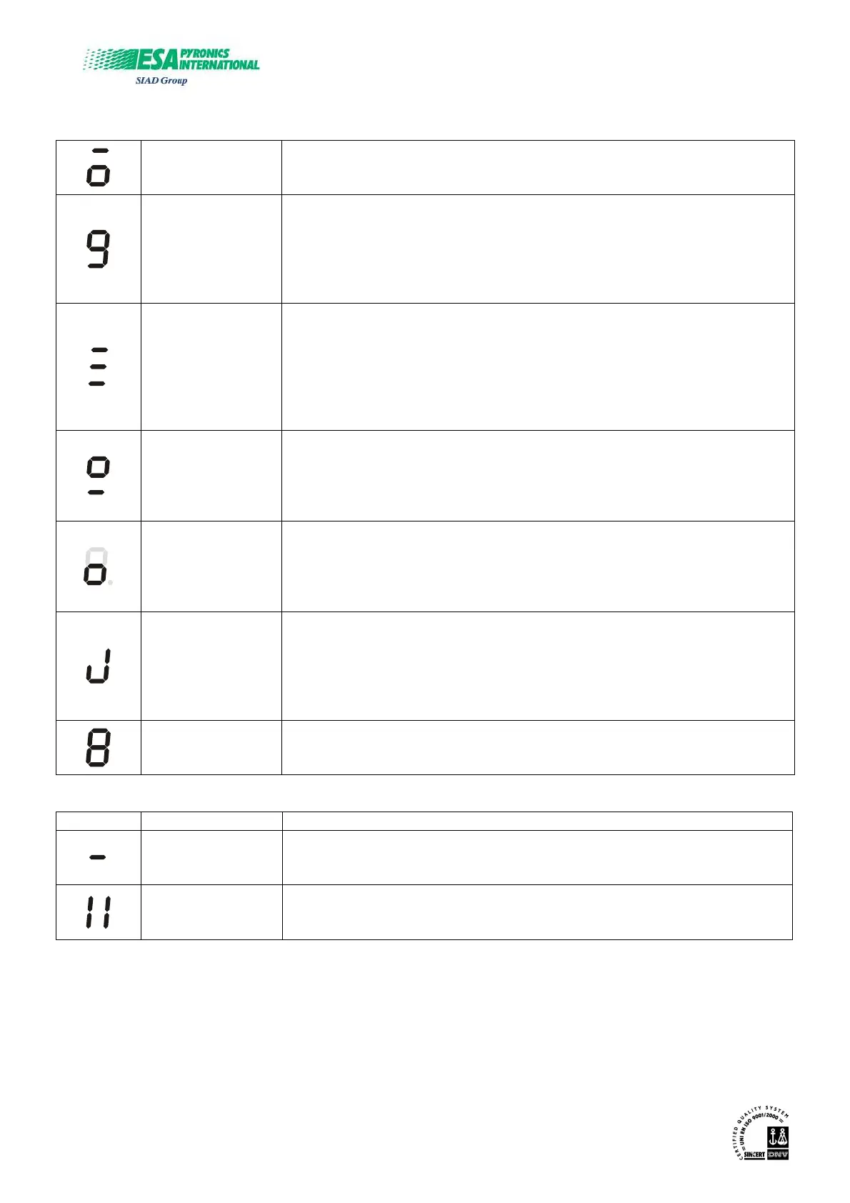
Configuration
DISPLAY INDICATION DESCRIPTION
FIXED
Configuration phase of the device via serial input (based on the
dedicated software). During this phase the execution of any other
operation is not allowed.
FIXED
Configuration phase of the device via infrared input (based on the
dedicated software). During this phase the execution of any other
operation is not allowed.
BARGRAPH
ESA ESTRO is equipped with a 5 LED bargraph to shows the value of flame detected signal in a range
from 0µA to 90µA. In case of detection currents higher than 90µA all the LED remain lighted.
 Loading...