• Cet appareil peut être utilisé par des enfants
âgés d’au moins 8 ans et par des personnes ayant
des capacités physiques, sensorielles ou mentales
réduites ou dénuées d’expérience ou de connaissance,
s’ils (si elles) sont correctement surveillé(e)s ou si des
instructions relatives à l’utilisation de l’appareil en toute
sécurité leur ont été données et si les risques encourus
ont été appréhendés. Les enfants ne doivent pas jouer
avec l’appareil. Le nettoyage et l’entretien par l’usager
ne doivent pas être effectués par des enfants sans
surveillance.
• Le raccordement du câble d’alimentation électrique
doit être effectué par un professionnel qualié,
conformément aux normes en vigueur, en prévoyant
un moyen de déconnexion dans les canalisations
xes.
• Si le câble d’alimentation est endommagé, il doit
être remplacé par un câble ou un ensemble spécial
disponible auprès du fabricant ou de son service
après vente.
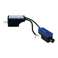
A. BRANCHEMENT ELECTRIQUE / ALARME
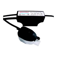
1. Alimentation électrique de la pompe
Déconnecter toute alimentation secteur pendant l’installation.
2. Branchement de l’alarme
La pompe dispose d’un contact de sécurité normalement fermé (NC) permettant d’arrêter l’unité
intérieure de climatisation en cas de risque de débordement des condensats (pensez à vérier les
spécications du climatiseur). Respectez le schéma 4 pour le branchement de l’alarme.
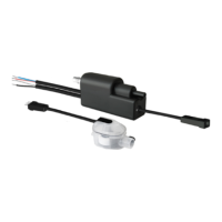
B. INSTALLATION DU BLOC DE DETECTION
Le bloc de détection (B) est alimenté en TRES BASSE TENSION par le bloc pompe. Il est impératif
d’utiliser le câble fourni. Un manchon coudé souple (G) permet de raccorder le bloc de détection au bac
• This appliance can be used by children form
8 years and above and people with reduced
physical, sensory or mental capabilities or lack of
experience and knowledge if they have been given
supervision or instruction concerning the use of the
appliance in a safe way and understand the hazards
involved. Children must not play with the appliance.
Cleaning and maintenance by the user must not be
performed by children.
• The connection of the power supply cable must be
carried out by a qualied professional, in accordance
with the standards in force, providing a means of
disconnection in the xed pipes.
• If the power cable is damaged, it must be replaced
with a special cable or assembly available from the
manufacturer or its service department.
A. ELECTRIC / ALARM CONNECTION
1. Pump power supply
Disconnect all AC power during installation.
2. Alarm connection
The pump has a normally closed (NC) safety contact to stop the indoor air conditioning unit if there is a
risk of condensate overow (remember to check the specications of the air conditioner). Follow gure
4 for the alarm connection.
B. DETECTION UNIT INSTALLATION
The detection unit (B) is supplied with VERY LOW VOLTAGE by the pump unit. It is imperative to use
the supplied cable. A exible elbow sleeve (G) is used to connect the detection unit to the air conditioner
tank. Suction is made through the 1.8m exible tube (H) with an internal diameter of 5 mm. Use 2
clamps (E) to permanently x this exible tube to the detection unit and the pump. Connect the vent
tube (D), internal diameter 4 mm, length 150 mm.
The detection unit must be placed and xed in a horizontal position - see gure 5 - by means of the
du climatiseur. L’aspiration se fait par le tube souple de 1,8m (H) ayant un diamètre interne de 5mm.
Utiliser 2 colliers de serrage (E) pour xer durablement ce tube souple au niveau du bloc de détection et
de la pompe. Raccorder le tube d’évent (D), diamètre interne 4mm, longueur 150mm.
Le bloc de détection doit être placé et xé en position horizontale - voir schéma 5 - au moyen du rail de
xation et de l’adhésif double-face (J).
Choisir le sens d’évacuation le mieux adapté à l’application, et obturer à l’aide du bouchon noir la sortie
d’évacuation inutilisée.
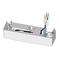
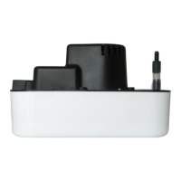
C. INSTALLATION DU BLOC POMPE
La pompe/coque (A) peut être xé dans le climatiseur, dans une goulotte ou en faux plafond. Le support
pompe (C) doit être xé avec des vis (et chevilles si nécessaire) adaptées au support. La pompe/
coque (A) doit ensuite être insérée dans le support pompe (C) et maintenue à l’aide d’un grand collier
de serrage (F) qui passera dans les encoches centrales du support pompe (C). Un espace libre doit
être préservé autour de la pompe/coque (A) pour permettre son refroidissement en cas de marche
prolongée. La pompe/coque (A) ne doit pas être recouverte (ni isolant, ni mousse expansive,etc.).
Le tube de refoulement (non fourni) doit avoir un diamètre 6x9mm pour être xé sur le raccord de sortie.
Utiliser un collier de serrage (E) an de xer durablement le tube de refoulement à la pompe.
L’installation du Stop Siphoning (I) est recommandée (voir schéma 8) pour éviter le phénomène de
décharge négative (voir schéma 7).
Respecter le sens d’écoulement indiqué par la èche sur le bloc pompe.
Si la sortie du tube de refoulement de la pompe se situe à un niveau inférieur au bloc pompe, et
dans le but d’éviter un effet de siphonage (décharge négative - voir schéma 7), il est impératif de:
- soit installer le Stop Siphoning (I) - voir schéma 8.
- soit raccorder la sortie du tube de refoulement à un tube de diamètre supérieur - voir schéma 9.
D. FONCTIONNEMENT ET ENTRETIEN
1. TEST DE FONCTIONNEMENT (recommandé)
Attention : Ne jamais faire fonctionner la pompe à sec plus des quelques secondes indispensables pour
la mise en service (risque de détérioration de la pompe)
• Verser de l’eau dans le bac du climatiseur sans excès (NB le tube d’évent doit rester sec)
• Vérier la mise en marche de la pompe et constater l’évacuation de l’eau par la pompe, puis l’arrêt
de celle-ci.
• Tester l’alarme en versant de l’eau en continu, même au delà de la mise en marche pompe pour que
le otteur active l’alarme (otteur niveau haut).
2. ENTRETIEN
Toute intervention sur la pompe de relevage de condensats doit être effectuée hors tension.
Lorsque la maintenance est nécessaire : Enlever le couvercle du bloc de détection, le ltre et le
otteur. Nettoyer l’intérieur du réservoir ainsi que le otteur avec une solution eau + javel 5%. Rincer
abondamment après toute utilisation d’un produit de nettoyage. Assurez-vous que le joint du couvercle
est bien dans son logement. Assurez vous que le otteur est bien positionné (aimant vers le haut) - voir
schéma 6.
plastic stand and the double-sided adhesive (J).
Choose the most suitable discharge direction for the application and seal the unused discharge outlet
with the black plug.
C. PUMP UNIT INSTALLATION
The pump/casing (A) can be mounted in the air conditioner, in a trunking or in a false ceiling. The pump
stand (C) must be xed with screws (and dowels if necessary) adapted to the support. The pump/casing
(A) must then be inserted into the pump stand (C) and fastened with a large clamp (F) that will pass
through the central notches of the pump stand (C). A free space must be left around the pump/casing
(A) to allow it to cool down in case of prolonged operation. The pump/casing (A) must not be covered
(no insulation, foam, etc.).
The discharge tube (not supplied) must have a diameter of 6x9mm to be xed on the outlet connection.
Use a hose clamp (E) to permanently x the discharge tube to the pump.
The installation of the Stop Siphoning (I) is recommended (see gure 8) to avoid the phenomenon of
negative discharge (see gure 7).
Observe the direction of ow indicated by the arrow on the pump unit.
If the end of the discharge tube is at a lower level than the pump unit, and in order to avoid a
siphoning effect (negative discharge - see gure7 - leading to abnormal noise and premature
wear of the pump), it is imperative to:
- install the Stop Siphoning SICCOM (I) - see gure 8.
- or connect the outlet of the discharge tube to a pipe with a larger diameter - see gure 9.
D. OPERATION AND MAINTENANCE
1. OPERATING TEST (recommended)
Caution: Never run the pump dry for more than the few seconds required for commissioning (risk of
damage to the pump).
• Pour water into the air conditioner tray without excess (NB the vent tube must remain dry).
• Check that the pump is switched on and that the water is drained from the pump and then switched
off.
• Test the alarm by pouring water continuously, even after the pump is switched on so that the oat
activates the alarm (high level oat).
2. MAINTENANCE
Any work on the condensate pump must be carried out with the power off.
When maintenance is required: Remove the cover of the detection unit, the lter and the oat. Clean
the inside of the reservoir and the oat with a water + 5% bleach solution. Rinse thoroughly after using
any cleaning product. Make sure that the cover gasket is in its housing. Make sure that the oat is
correctly positioned (magnet upwards) - see diagram 6.
FR
EN
 Loading...