LECTOR
®
SICK AGWaldkirchGermanywww.sick.com2
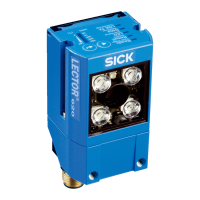
Allowing for Reading Angle
typical 20°
Selection of skew angle, depending on the application
> Tilt the Lector
®
620 away from the plane that is
perpendicular to the surface of the code to avoid as many
be 20°.
For codes created on metal, e.g., by dot peening, an angle of
be advisable.
>
with the device powered and working.
CDB620-001 Connection Module
> Mount the CDB620-001 connection module in the vicinity
of the Lector
®
620. If you are using the serial AUX interface
(RS-232), we recommend a maximum distance of 5 m.
Mount the Lector
®
620 in such a way that the device
remains accessible at all times. See & CDB620-001
Connection Module Operating Instructions (No. 8012119),
which are supplied in printed form with the connection
module.
Step 2: Electrical Installation
.
The Lector
®
620 may only be connected to or disconnected
from other devices when there is no power to the system.
Otherwise, the devices may be damaged.
When using connecting or extension cables with an open
end, make sure that bare wire ends are not touching (risk of
short-circuit when the supply voltage is switched on). Wires
must be properly insulated from each other.
Wire cross-sections in the supply cable from the customer's
power system should be designed in accordance with the
applicable standards.
If the supply voltage for the Lector
®
620 is not supplied
via a SICK connection module, the Lector
®
620 must be
protected by a separate 2.0 A slow-blow fuse at the start of
the supply circuit.
All circuits connected to the Lector
®
620 must be designed
as SELV circuits. The power supply or power supply unit
must satisfy SELV requirements in accordance with the
currently applicable EN 60950-1. (SELV = Safety Extra Low
Voltage).
a DANGER
Electrical current poses a serious risk of injury or damage!
The Lector
®
620 is designed to be operated in a system
with professional grounding of all connected devices and
mounting surfaces to the same ground potential.
Incorrect grounding of the Lector
®
620 can result in
equipotential bonding currents between the Lector
®
620
and other grounded devices in the system. This can lead
to hazardous voltages being applied to the metal housing,
cause devices to malfunction or sustain irreparable damage,
and damage the cable shield as a result of heat rise, thereby
Ensure that the ground potential is the same at all
grounding points.
If the cable insulation is damaged, disconnect the power
supply immediately and have the damage repaired.
> See the "Electrical Installation" chapter in the
& Lector
®
620 Image-Based Code Reader Technical
Information on the product page at:
www.mysick.com/en/lector62x
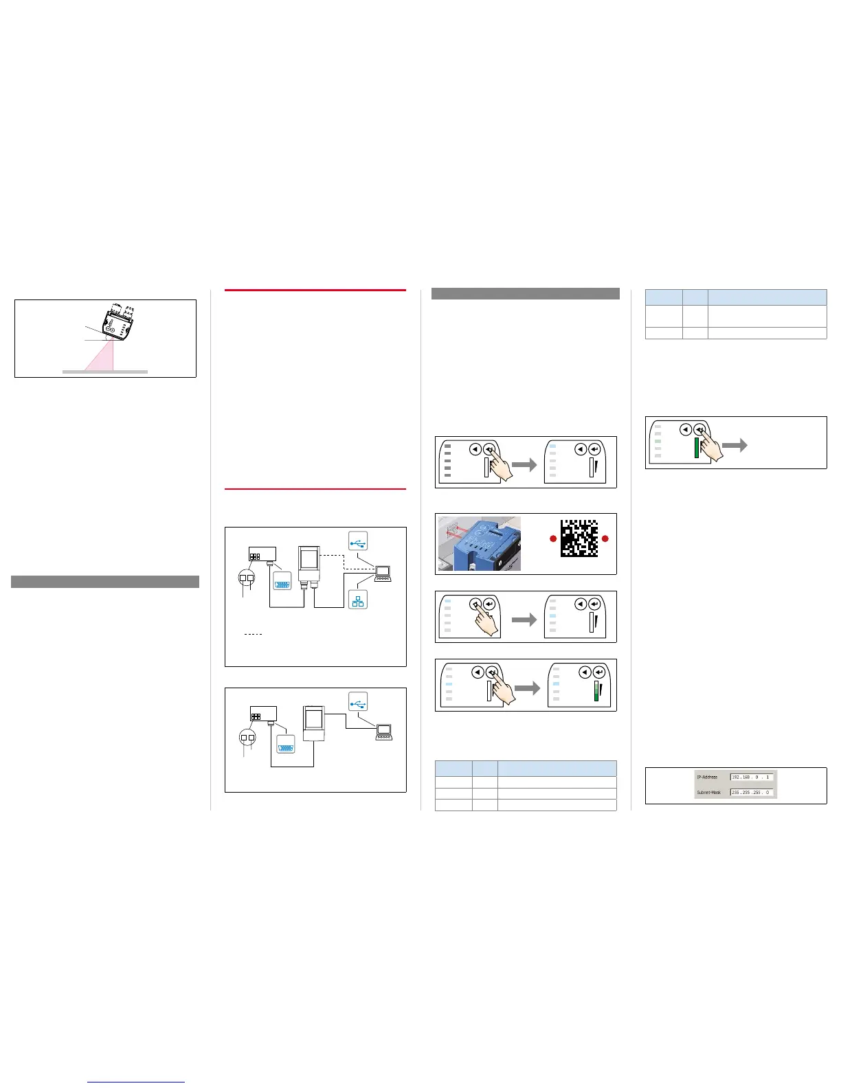
1. Connect the communications interface of the Lector
®
620
(Ethernet or USB, ECO variant: USB) to the PC.
2. Connect the Lector
®
620 to the power supply.
Connection module
CDB620-001
SOPASSOPAS
Lector
®
620
1
2
Image
display
Diagnostcis
“Power”
“Ethernet”
“USB”
ICR620x-xxxYxx (Y = 5)
Swivel connector unit with 2 M12 cylindrical connectors
e.g. cable
no. 2055419
(2 m)
e.g. cable
no. 6034414
(2 m)
SerialSerial
...
...
alternative for configuration/image display,
e.g. cable no. 6036106 (2 m)
EthernetEthernet
USBUSB
Lector
®
620 Professional, High Speed, DPM Plus and OCR with swivel
connector
Anschlussmodul
CDB620-001
SOPASSOPAS
Lector
®
620 ECO
1
2
Image-
display
Diagnostics
“Power”
SerialSerial
...
...
e.g. cable
no. 6036106
(2 m)
ICR620x-xxxYxx (Y = 0)
Cable with 15-pin D-Sub HD male connector
“USB”
USBUSB
Lector
®
620 ECO with cable outlet
a.
The two function buttons and the LEDs with their second
display level are used for adjusting the reading performance
of the Lector
®
620 without a PC.
The
®
620 uses the Auto-Setup function to adjust
itself automatically to the lighting conditions and quality
presented code (not applicable to Pharmacode and OCR).
The Professional, High Speed, DPM Plus and OCR variants
also adjust to the working distance. The values calculated for
the three parameter modules, or two parameter modules in
the case of the ECO variant, are permanently stored (default),
1. Start "Edit" mode.
3 sec
Ready
Read Diagn
Result
TeachIn
LED
Auto-Setup
Data
Autofocus
LNK TX
Userdefined
300
200
100
70
40
100
0
[mm]
[%]
Ready
Read Diagn
Result
TeachIn
LED
Auto-Setup
Data
Autofocus
LNK TX
Userdefined
300
200
100
70
40
100
0
[mm]
[%]
O
2. Align the Lector
®
620 with the code.
The ECO variant has no aiming laser.
3. Select Auto-Setup.
Ready
Read Diagn
Result
TeachIn
LED
Auto-Setup
Data
Autofocus
LNK TX
Userdefined
300
200
100
70
40
100
0
[mm]
[%]
Ready
Read Diagn
Result
TeachIn
LED
Auto-Setup
Data
Autofocus
LNK TX
Userdefined
300
200
100
70
40
100
0
[mm]
[%]
O
O
2 x short
4. Start Auto-Setup.
1 x short
Ready
Read Diagn
Result
TeachIn
LED
Auto-Setup
Data
Autofocus
LNK TX
Userdefined
300
200
100
70
40
100
0
[mm]
[%]
Ö
Ready
Read Diagn
Result
TeachIn
LED
Auto-Setup
Data
Autofocus
LNK TX
Userdefined
300
200
100
70
40
100
0
[mm]
[%]
O
Feedback from Lector
®
620 during Auto-Setup
The bar display shows the progress of the Auto-Setup function
The color of the LED now signals the success status.
LED
Auto-Setup
Color Status
O
Blue
Auto-Setup selected
Blue
Auto-Setup started
O
Green
LED
Auto-Setup
Color Status
O
Yellow
Auto-Setup partially successful
(in at least one of the 3 modules or
2 modules in the case of the ECO variant)
O
Red
Auto-Setup was unsuccessful
O = illuminated;
Important
> If the read result is inadequate ("Auto-Setup" LED lights
up yellow or red), check the alignment and distance of the
Lector
®
620 in relation to the code ( "Step 1: Mounting
and Alignment") and perform Auto-Setup again.
5. Exit "Edit" mode. Save parameters.
Ready
Read Diagn
Result
TeachIn
LED
Auto-Setup
Data
Autofocus
LNK TX
Userdefined
300
200
100
70
40
100
0
[mm]
[%]
O
3 sec
Save
parameters
Alternatively, the Lector
®
620 saves the parameters
automatically if 5 minutes elapse without a pushbutton being
pressed, and it returns to read mode.
b.
the Lector
®
620 parameters to the application and to perform
diagnostics in the event of an error. The Lector
®
620 supports
this process by displaying the images it has recorded in the
SOPAS software (SOPAS requirement: V. 2.34 or higher).
If the reading performance of the Lector
®
620 has been
adapted without a PC, SOPAS is generally used to continue
data interface, etc.).
1. Download and install the latest version of the SOPAS ET
the software:
www.mysick.com/en/SOPAS_ET
by following the instructions provided there. In this case,
select the "Complete" option as suggested by the installer.
Administrator rights may be required on the PC to install
the software.
2. Start the "Single Device" program option after completing
the installation. Path: Start > Programs > SICK > SOPAS ET
Engineering Tool > SOPAS (Single Device).
3. Establish a connection between the software and the
Lector
®
620 via Ethernet or USB (ECO variant: USB).
The connection wizard starts automatically.
Lector
®
620:
 Loading...