SICK AGWaldkirchGermanywww.sick.com LECTOR
®
3
4. Select the appropriate Lector
®
620 from the list of available
devices. SOPAS establishes communication with the
Lector
®
620 and loads the associated device description
®
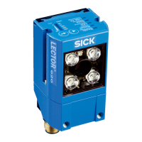
620. The program window, which is
divided into three sections, opens.
Wizard
and help
Image
Configuration
bars
> Start the
Auto-Setup wizard on the left in the program
window and follow the instructions in the dialog box.
The Lector
®
620 uses the Auto-Setup function to adjust
itself automatically to the lighting conditions and quality
presented code (not applicable to Pharmacode
and OCR). The Professional, High Speed, DPM Plus and
OCR variants also adjust to the working distance.
The values calculated for the three modules, or two
modules in the case of the ECO variant, are stored
bars
CAmerA & IllumInAtIon and CodeS.
1. For custom optimization of the image and code settings of
the Lector
®
620, click the CAmerA & IllumInAtIon and CodeS
values accordingly.
2. To make the changes directly visible, go to the image
display window (Online Images) and click the
edIt button.
The Lector
®
620 now starts recording images and uses the
current settings to decode them.
The switching inputs and outputs as well as data output
via the host interface are deactivated in
edIt mode.
3. Enter settings for additional functions such as reading clock,
read result formats, data interface, etc.
4. Go to the image display window (Online Images), click
the
operAtIon button and test the settings in read mode
(real operation).
OCR Variant Only:
> For optical character recognition (OCR), start the oCr
Setup wizard on the left of the program window and follow
the instructions in the dialog box.
>
Parameter set in Lector
®
620: Click the
button
button.
Important
To put the Lector
®
620 into operation on a network
(e.g., CAN bus) together with other SICK products, select the
SOPAS program option. Path: Start > Programs > SICK >
SOPAS Engineering Tool > SOPAS.
Device Description
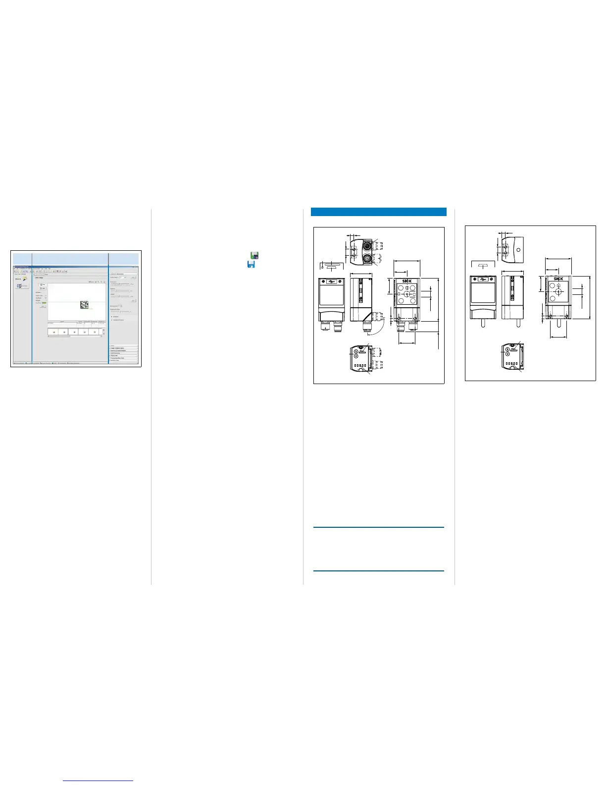
Device Layout – Lector
®
620 with Swivel Connector
Ready
Read Diagn
Result
TeachIn
LED
Auto-Setup
Data
Autofocus
LNK TX
Userdefined
300
200
100
70
40
100
0
[mm]
[%]
1
2
3
5
a
4
1
6
7
8
9
ß
á
à
â
26.5
35.6
Ø 10
All dimensions in mm
Lector
®
620 Professional, High Speed, DPM Plus and OCR
1 M5 blind tapped holes, 5 mm deep (4 x), for mounting the
Lector
®
620
2 "Ethernet" connection (4-pin M12 female connector, D-coded)
3 "Power/Serial Data/CAN/I/O" connection (17-pin M12 male connector,
A-coded)
4 M5 sliding nuts, 5 mm deep (2 x), for mounting the Lector
®
620
(alternative)
5 Swivel connector
6 Reading window
7 Function buttons (2 x)
8 Bar graph display
9 RGB LEDs for status indication (2 levels), 5 x
à USB port, 5-pin female connector, Micro B type
á Slot for microSD memory card
á LED for microSD memory card
Important
The dimensions in the above drawing are not applicable to type
ICR620D-T51503 (part no. 1064256). The corresponding,
differing drawing can be downloaded from the product page for
the Lector
®
620: www.mysick.com/en/lector62x
NOTE
Risk of damaging the swivel connector
The connector may be moved up to 180° from end point to
end point of the stop.
The ECO variant has no swivel connector.
Device Layout – Lector
®
620 with Cable Outlet
Ready
Read Diagn
Result
TeachIn
LED
Auto-Setup
Data
Autofocus
LNK TX
Userdefined
300
200
100
70
40
100
0
[mm]
[%]
1
2
1
3
4
5
6
8
7
9
26.5
35.6
10
4.8
43
21.5
26
71
Ø 10
All dimensions in mm
Lector
®
620 ECO
1 M5 blind tapped holes, 5 mm deep (4 x), for mounting the
Lector
®
620
2 M5 sliding nuts, 5 mm deep (2 x), for mounting the Lector
®
620
(alternative)
3 Reading window
4 Function buttons (2 x)
5 Bar graph display
6 RGB LEDs for status indication (2 levels), 5 x
7 Cable (0.9 m) with 15-pin D-Sub HD male connector ("Power/Serial
Data/CAN/I/O")
8
9 USB port, 5-pin female connector, Micro B type
Type Code
The device list on the product page of the Lector
®
620
(www.mysick.com/en/lector62x)
(variant allocation) based on the type label of the device.
 Loading...