EasyManua.ls Logo

SICK safeRS3 User Manual

SICK safeRS3
120 pages
To Next Page IconTo Next Page
Page #1 background imageLoading...
Page #1 background image
O P E R A T I N G I N S T R U C T I O N S
safeRS3
Safe Radar System

Table of Contents

Questions and Answers:

SICK safeRS3 Specifications

General IconGeneral
BrandSICK
ModelsafeRS3
CategoryRadar
LanguageEnglish

Summary

Glossary of Terms

This Manual

Information on this Manual

Details about the manual's purpose, scope, and related documentation.

Objectives of this Instruction Manual

Explains how to integrate, install, use, and maintain the safeRS3 system safely.

Obligations with regard to this Manual

User obligations regarding manual care, storage, and accessibility.

Provided Documentation

Lists related documents like technical information for PROFIsafe and Modbus.

Intended Users of this Instruction Manual

Identifies recipients: machinery manufacturer, system installer, maintenance technician.

Safety

Safety Information

General safety warnings and notices for users and equipment.

Safety Messages

Defines WARNING and NOTICE symbols and their implications.

Safety Symbols on the Product

Explains symbols on the product and their relation to manual consultation.

Personnel Skills

Outlines required skills for machinery manufacturers, installers, and technicians.

Safety Assessment

Requirement for safety assessment as per Machinery Directive before device use.

Intended Use

Details safeRS3 certifications, functions, and applications.

EMC-Compliant Electrical Installation

Guidelines for electrical installation to comply with standards and directives.

General Warnings

Important warnings about installation, configuration, and system limits.

Warnings for the Restart Prevention Function

Specific warnings related to restart prevention function guarantees and installation.

Responsibility

Defines responsibilities of the machinery manufacturer and system installer.

Limits

System limitations in detecting immobile or non-breathing people.

Disposal

Guidance on safe disposal of the product according to regulations.

Conformity

Information on standards, directives, and CE conformity.

Standards and Directives

Lists applicable directives and standards for the safeRS3 system.

CE

Manufacturer's statement of conformity with EU directives.

Other Conformities and National Configurations

Information on additional conformities and national configurations.

Get to Know safeRS3

safeRS3

General introduction to the safeRS3 system.

Definition

Defines safeRS3 as an active protection radar system for monitoring dangerous areas.

Special Features

Highlights key features like distance/angle detection and protective fields.

Main Components

Describes the system composition: control and sensors.

Control - Sensor Communication

Explains communication between control and sensors via CAN bus.

Control - Machinery Communication

Details communication between control and machinery via I/O or Fieldbus.

Applications

How safeRS3 integrates with machinery control systems for safety.

safeRS3 Controls

Overview of the different control units supported by safeRS3.

Control Supported

Differentiates between PROFINET and I/O control types.

Functions

Lists the core functions performed by the safeRS3 control unit.

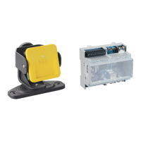
Structures

Details the physical structure and components of the control units.

System Status LEDs

Explains the meaning of system status LEDs on the sensors.

Fieldbus Status LEDs

Explains the meaning of PROFINET/PROFIsafe Fieldbus status LEDs.

Inputs

Describes the system's digital inputs and their programming functions.

Input Variable Behavior

Explains how input variables behave under different conditions.

SNS Input

Details the SNS input for checking input status and diagnostic function.

Outputs

Describes the four digital OSSD outputs and their functions.

External Resistor for OSSD Outputs

Information on using external resistors for OSSD outputs.

safeRS3 Sensor

Overview of the safeRS3 sensor unit.

Functions

Lists the primary functions performed by the safeRS3 sensor.

2-Axes Structure

Details the mechanical structure of the sensor with 2-axis rotation.

3-Axes Structure

Details the mechanical structure of the sensor with 3-axis rotation.

Status LED

Explains the different states indicated by the sensor's status LED.

safeRS3 Designer Application

Main functions and usage of the configuration software.

Functions

Lists the main functions of the safeRS3 Designer application.

safeRS3 Designer Application Usage

How to connect and use the safeRS3 Designer application.

Access

Explains password protection and access levels for application functions.

Main Menu

Overview of the main menu structure and functions within the application.

Fieldbus Communication

Information on Fieldbus communication support and capabilities.

Fieldbus Support

Details which control supports Fieldbus communication.

Communication with the Machinery

Describes actions possible via Fieldbus communication.

Data Exchanged Through Fieldbus

Lists data types exchanged via Fieldbus communication.

Modbus Communication

Information on Modbus communication support and data exchange.

Modbus Support

Details Modbus communication availability and requirements.

Modbus Communication Enabling

Steps to enable Modbus communication in the Designer application.

Data Exchanged Through Modbus

Lists data types exchanged via Modbus communication.

System Configuration

Procedures for system parameter configuration and dynamic adjustments.

System Configuration

How to modify control parameters and save configurations.

Dynamic System Configuration

Real-time adjustment of system parameters and switching between presets.

Dynamic System Configuration Activation

Methods for activating dynamic system configuration.

Dynamic Configuration Through the Digital Inputs

Using digital inputs to activate dynamic system configuration.

Dynamic Configuration Through the Safety Fieldbus

Using safety Fieldbus to activate dynamic system configuration.

Safe Configuration Change

How safe configuration changes are handled by the system.

Functioning Principles

Sensor Functioning Principles

Explains how the FMCW radar sensor detects motion and targets.

Introduction

Introduces the FMCW radar technology used by the safeRS3 sensor.

Factors That Influence the Reflected Signal

Details object characteristics affecting radar signal reflection.

Detected and Missed Objects

How the algorithm handles moving vs. static objects and filtering.

Protective Fields

Defines and explains the concept of protective fields.

Introduction

Introduces protective fields and their dedicated detection signals.

Protective Field Parameters

Lists programmable parameters for each protective field.

Angular Coverage

Defines the range and requirements for angular coverage of protective fields.

Detection Distance

Rules for setting detection distances between protective fields.

Protective Fields Dependency and Detection Signal Generation

How field dependencies affect signal generation and output deactivation.

Independent Protective Fields: A Use Case

Example of using independent protective fields for operational efficiency.

Safety Working Modes and Safety Functions

Explains available safety working modes and their associated functions.

Introduction

Introduces the safety working modes and functions.

Safety Working Modes

Details the "Both", "Always access detection", and "Always restart prevention" modes.

Safety Working Mode: Both (default)

Explanation of the default "Both" safety working mode.

Introduction

Introduces the "Both" safety working mode.

Safety Function: Access Detection

How access detection functions within the "Both" mode.

Safety Function: Restart Prevention

How restart prevention functions within the "Both" mode.

Restart Timeout Parameter

Configuration of the restart timeout parameter.

Safety Working Mode: Always Access Detection

Explanation of the "Always access detection" mode.

Safety Function: Access Detection

How access detection functions in this mode.

TOFF Parameter

Configuration of the TOFF parameter for this mode.

Safety Working Mode: Always Restart Prevention

Explanation of the "Always restart prevention" mode.

Safety Function: Restart Prevention

How restart prevention functions in this mode.

Restart Timeout Parameter

Configuration of the restart timeout parameter for this mode.

Restart Prevention Function: Static Object Detection Option

Details the static object detection option for restart prevention.

Introduction

Introduction to the static object detection option.

Availability

Information on firmware requirements for static object detection.

Possible Applications

Use cases for the static object detection option.

Operation

How the static object detection option operates.

Restart Timeout Parameter

Minimum value for restart timeout when static object detection is enabled.

Features of the Restart Prevention Function

Detailed features and limitations of the restart prevention function.

Cases of Non-Guaranteed Function

Scenarios where restart prevention is not guaranteed.

Types of Managed Restart

Assesses automatic vs. manual restart prevention safety levels.

Precautions for Preventing Unexpected Restarting

Measures to prevent unexpected restarts, especially at low heights.

Configure the Restart Prevention Function

Steps to configure automatic, manual, and safe manual restart.

Muting

Explanation of the muting function and its configuration.

Description

Defines muting as a temporary suspension of safety functions.

Muting Enabling

How to enable muting via digital inputs or Fieldbus.

Muting Activation Conditions

Conditions required for the muting function to activate.

Enable Muting Signal Characteristics

Requirements for muting signal logic and timing.

Muting Status

Feedback signal for muting status.

Anti-Tampering Functions: Anti-rotation around Axes

Functionality to detect sensor rotation around its axes.

Anti-Rotation Around Axes

How the sensor detects rotation and sends tamper alerts.

Disable the Anti-Rotation Around Axes Function

Procedures and warnings for disabling the anti-rotation function.

Checks When the Anti-Rotation Around Axes Function is Disabled

Checks to perform when the anti-rotation function is disabled.

When to Disable

Situations where disabling the anti-rotation function might be necessary.

Anti-Tampering Functions: Anti-masking

Functionality to detect obstructions in the sensor's field of view.

Masking Signal

How masking signals are generated and their effect.

Environment Memorization Process

Process of the sensor memorizing its surrounding environment.

Causes of Masking

Common causes that trigger masking signals.

Masking Signal When the System is Turned On

False masking signals due to temperature fluctuations on startup.

Settings

Configuration options for anti-masking distance and sensitivity.

Checks When the Anti-Masking Function is Disabled

Checks to perform when the anti-masking function is disabled.

When to Disable

Conditions under which the anti-masking function should be disabled.

Sensor Position

Basic Concepts

Fundamental factors influencing sensor positioning.

Determining Factors

Factors like field of view and dangerous area depth.

Sensor Installation Height

Definition of sensor installation height.

Sensor Inclination

Definition and examples of sensor inclination angles.

Sensor Field of View

How the sensor's view is defined and its dimensions.

Types of Field of View

Selecting angular coverage for each field.

Areas and Dimensions of the Field of View

Defines protective and tolerance areas of the FOV.

Dimensions for the Access Detection Function

FOV dimensions related to access detection.

Dimensions for the Restart Prevention Function

FOV dimensions related to restart prevention.

Position of the Field of View

How LED position relates to actual FOV position.

Dangerous Area Calculation

Method for calculating the dangerous area depth.

Introduction

Introduction to dangerous area calculation standards.

Formula

The formula for calculating dangerous area depth (S = K*T+C).

Calculation of Range of Distances

Formulas for calculating detection ranges based on inclination and height.

Introduction

Introduction to range calculation formulas.

Legend

Legend for variables used in range calculation formulas.

Installation Configurations

Three configurations based on sensor inclination (α).

Calculate the Range of Distances

Table showing range of distances for different configurations.

Calculate the Real Detection Distance

Calculating the actual detection distance (Dalarm).

Sensor Position Recommendations

Guidelines for optimal sensor placement.

For Access Detection Function

Recommendations for positioning sensors for access detection.

For Access Control of an Entrance

Recommendations for controlling entrance access.

Installations on Moving Elements

Specific considerations for mounting on moving parts.

Introduction

Mounting sensors on moving vehicles or machinery parts.

Speed Limits

Guaranteed detection speed limits for moving elements.

Detection Signal Generation Conditions

Conditions for generating detection signals on moving parts.

Prevention of Unexpected Restart

Methods to prevent unexpected restarts on moving parts.

Recommendations for Positioning the Sensor

Positioning guidance for sensors on moving elements.

Outdoor Installations

Considerations for installing sensors outdoors.

Position Exposed to Precipitation

Precautions for positions exposed to precipitation.

Recommendations for Covering the Sensor

Guidelines for creating sensor covers.

Recommendations for Positioning the Sensor

Positioning recommendations for outdoor installations.

Position Not Exposed to Precipitation

No special precautions needed if not exposed to precipitation.

Installation and Use Procedures

Before Installation

Preparatory steps before installing the system.

Materials Required

Lists all necessary materials for installation.

Operating System Required

Specifies required operating systems for the software.

Install the safeRS3 Designer Application

Step-by-step guide to install the configuration software.

Initiate safeRS3

Initial steps to start and configure the safeRS3 system.

Install and Configure safeRS3

Detailed procedures for installing and configuring the system.

Install the Control

Steps for mounting and making electrical connections for the control unit.

Synchronize the Controls

Procedure to synchronize multiple control units.

Define the Area to be Monitored

Steps to define the monitored area and configure sensors.

Configure the Inputs and Outputs

Configuration of digital inputs and outputs for various functions.

Install the Sensors

Physical installation steps for the sensors.

Mount Bracket for Z-Axis Rotation (Roll)

Instructions for mounting the optional z-axis rotation bracket.

Examples of Sensor Installation

Visual examples of floor and wall sensor installations.

Connect the Control to the Sensors

Wiring the control unit to the sensors in a chain.

Assign the Node IDs

Methods for assigning unique Node IDs to sensors.

Chain Examples

Diagrams showing sensor chain configurations.

Save and Print the Configuration

Procedures for saving and printing the system configuration report.

Set the Control Ethernet Parameters

Configuring Ethernet settings for the control unit.

Validate the Safety Functions

Procedures for validating system safety functions.

Validation

General overview of the validation process.

Validate the Access Detection Function

Steps to validate the access detection function.

Example of Access Points

Illustrates access points for testing the FOV.

Validate the Restart Prevention Function

Steps to validate the restart prevention function.

Example of Stopping Points

Illustrates stopping points for testing.

Validate the System with safeRS3 Designer

Using the Designer app to validate sensor field of view.

Troubleshooting Validation

Solutions for common validation problems.

Manage the Configuration

Procedures for managing system configurations.

Configuration Reports

Information contained in configuration reports.

Change the Configuration

How to modify system configuration parameters.

Back Up the Configuration

Steps to back up the current system configuration.

Load a Configuration

How to restore a previously saved configuration.

Display Previous Configurations

Accessing and viewing past configuration reports.

Other Functions

Miscellaneous functions available in the system.

Change Language

How to change the system language.

Application Type Selection

Selecting the appropriate application type.

Locate the Area with Detected Motion

Visualizing detected motion areas using the validation tool.

Restore Factory Default Settings

Resetting parameters to factory defaults.

Identify a Sensor

Procedure to identify a specific sensor.

Change Network Parameters

Modifying network settings like IP address.

Change Modbus Parameters

Modifying Modbus communication settings.

Change Fieldbus Parameters

Modifying Fieldbus communication settings.

Maintenance and Troubleshooting

Troubleshooting

General troubleshooting guide for system issues.

Control LED

Interpreting control unit LED status for error diagnosis.

Sensor LED

Interpreting sensor LED status for error diagnosis.

Other Problems

Troubleshooting for various other system issues.

Event Log Management

Managing and downloading system event logs.

Introduction

Introduction to event logging capabilities.

Download the System Log

Steps to download the system log file.

Log File Sections

Description of the two sections in the log file.

Log Line Structure

Format of each line within the log file.

Timestamp (Seconds Counter from the Latest Boot)

Explanation of relative timestamps from the latest boot.

Timestamp (Absolute/Relative Value)

Explanation of absolute and relative timestamp formats.

Event Description

Details on event descriptions and parameters.

Log File Example

An example of a system event log file.

Event List

List of events and their types.

Verbosity Level

Setting verbosity levels for system logs.

Verbosity Level for Detection Access and Exit Events

Specific verbosity levels for detection events.

INFO Events

Details about informational events logged by the system.

System Boot

Event logged when the system powers up.

System Configuration

Event logged when the system is configured.

Factory Reset

Event logged upon factory reset.

Stop Signal

Event for changes in the Stop Signal status.

Restart Signal

Event for waiting or receiving a restart signal.

Detection Access

Event logged when motion is detected.

Detection Exit

Event logged when detection signals return to default.

Dynamic Configuration in Use

Event logged on changes to dynamic configuration.

Muting Status

Event logged for changes in muting status.

Fieldbus Connection

Event for Fieldbus connection status.

Modbus Connection

Event for Modbus connection status.

Session Authentication

Event for session authentication status.

Validation

Event for validation activity start/end.

Log Download

Event for log download activity.

ERROR Events (Control)

Diagnostic errors detected by the control unit.

Introduction

Introduction to control error events.

Temperature Errors (TEMPERATURE ERROR)

Errors related to board or chip temperature.

Control Voltage Errors (POWER ERROR)

Errors related to control unit voltage levels.

Peripheral Error (PERIPHERAL ERROR)

Errors detected in control peripherals or memories.

Configuration Errors (FEE ERROR)

Errors indicating incomplete system configuration.

Output Errors (OSSD ERROR)

Errors related to OSSD output circuits.

Flash Errors (FLASH ERROR)

Errors related to the external flash memory.

Dynamic Configuration Error (DYNAMIC CONFIGURATION ERROR)

Errors with invalid dynamic configuration IDs.

Internal Communication Error (INTERNAL COMMUNICATION ERROR)

Errors in internal communication within the control.

Input Redundancy Error (INPUT REDUNDANCY ERROR)

Errors in redundant input channels.

Fieldbus Error (FIELDBUS ERROR)

Errors related to Fieldbus communication establishment.

RAM Error (RAM ERROR)

Errors detected during RAM integrity checks.

Sensor Configuration Errors (SENSOR CONFIGURATION ERROR)

Errors when sensors fail to receive correct configuration.

ERROR Events (Sensor)

Diagnostic errors detected by the safeRS3 Sensor.

Introduction

Introduction to sensor error events.

Misconfiguration Error (MISCONFIGURATION ERROR)

Errors due to invalid or missing sensor configuration.

Status Error and Fault (STATUS ERROR/FAULT ERROR)

Errors indicating an invalid sensor status or fault condition.

Protocol Error (PROTOCOL ERROR)

Errors from receiving unknown command formats.

Sensor Voltage Errors (POWER ERROR)

Errors related to sensor voltage levels.

Anti-Tampering Sensor (TAMPER ERROR)

Errors detected due to sensor tampering or rotation.

Signal Error (SIGNAL ERROR)

Errors detected in the RF signals part of the sensor.

Temperature Errors (TEMPERATURE ERROR)

Errors related to sensor component temperatures.

MSS Error and DSS Error (MSS ERROR/DSS ERROR)

Errors related to internal micro-controllers (MSS/DSS).

ERROR Events (CAN Bus)

Diagnostic errors detected on the CAN bus communication.

Introduction

Introduction to CAN bus error events.

CAN Errors (CAN ERROR)

Specific CAN bus error types and their meanings.

Cleaning and Spare Parts

Procedures for cleaning and information on spare parts.

Cleaning

Guidelines for cleaning the sensor to maintain performance.

Spare Parts

List of available spare parts for the system.

Technical References

Technical Data

General specifications and technical data for the system.

General Specifications

Detailed technical specifications of the safeRS3 system.

Safety Parameters

Safety-related parameters like SIL and PL levels.

Ethernet Connection (if available)

Default Ethernet connection parameters.

Control Features

Features and characteristics of the safeRS3 control unit.

Sensor Features

Features and specifications of the safeRS3 sensor.

CAN Bus Cables Recommended Specifications

Recommended specifications for CAN bus cables.

Tamper-Proof Screws Specifications

Specifications for tamper-proof screws used in installation.

Non Tamper-Proof Screws Specifications

Specifications for non-tamper-proof screws.

Bottom Screws Specifications

Specifications for bottom mounting screws.

Terminal Blocks and Connector Pin-outs

Pin-out diagrams and descriptions for terminal blocks and connectors.

Digital Inputs and Outputs Terminal Block

Pin-out for the digital I/O terminal block.

Voltage and Current Limits for Digital Inputs

Voltage and current limits for digital inputs.

Power Supply Terminal Block

Pin-out for the power supply terminal block.

CAN Bus Terminal Block

Pin-out for the CAN bus terminal block.

Connectors M12 CAN Bus

Pin-out details for M12 CAN bus connectors.

Electrical Connections

Diagrams for connecting the system to machinery and external components.

Connection of Safety Outputs to the Machinery Control System

Wiring safety outputs to the machinery's control system.

Connection of Safety Outputs to an External Safety Relay

Wiring safety outputs to an external safety relay.

Connection of Stop Signal (Emergency Button)

Wiring an emergency stop button to the system.

Connection of Restart Signal

Wiring a restart signal button to the system.

Connection of the Muting Input and Output (One Group of Sensors)

Wiring muting for a single group of sensors.

Detection Signal 2 Connection

Wiring for detection signal 2.

Diagnostic Output Connection

Wiring for a diagnostic output signal.

Parameters

Detailed list of configurable system parameters.

Parameter List

Comprehensive list of parameters with min, max, and default values.

Digital Input Signals

Explanation of digital input signals like Stop and Muting.

Stop Signal

Details the stop signal's behavior and its effect on detection signals.

Muting (with/without pulse)

Explains muting signal characteristics with and without pulse.

Restart Signal

Details the restart signal's behavior and its effect on detection signals.

Active Dynamic Configuration

How active dynamic configuration works with inputs.

Appendix

System Software

Information related to the system's software.

Introduction

Purpose of the appendix regarding system software.

Configuration

How system configuration is performed using the Designer application.

Competence

Required competence for installation and configuration.

Installation Instructions

Information on firmware deployment and setup installer.

Outstanding Anomalies

Known software/firmware anomalies or bugs.

Backward Compatibility

Assurance of backward compatibility for the system.

Change Control

Process for suggesting and evaluating changes.

Implemented Security Measures

Security measures for firmware upgrade packages.

Disposal

Guidelines for proper disposal of the product.