Company Confidential s Com
Copyright 2005© Siemens AG
Page 7 of 37
Service Repair Documentation
Level 2.5e – C75
Release 1.0
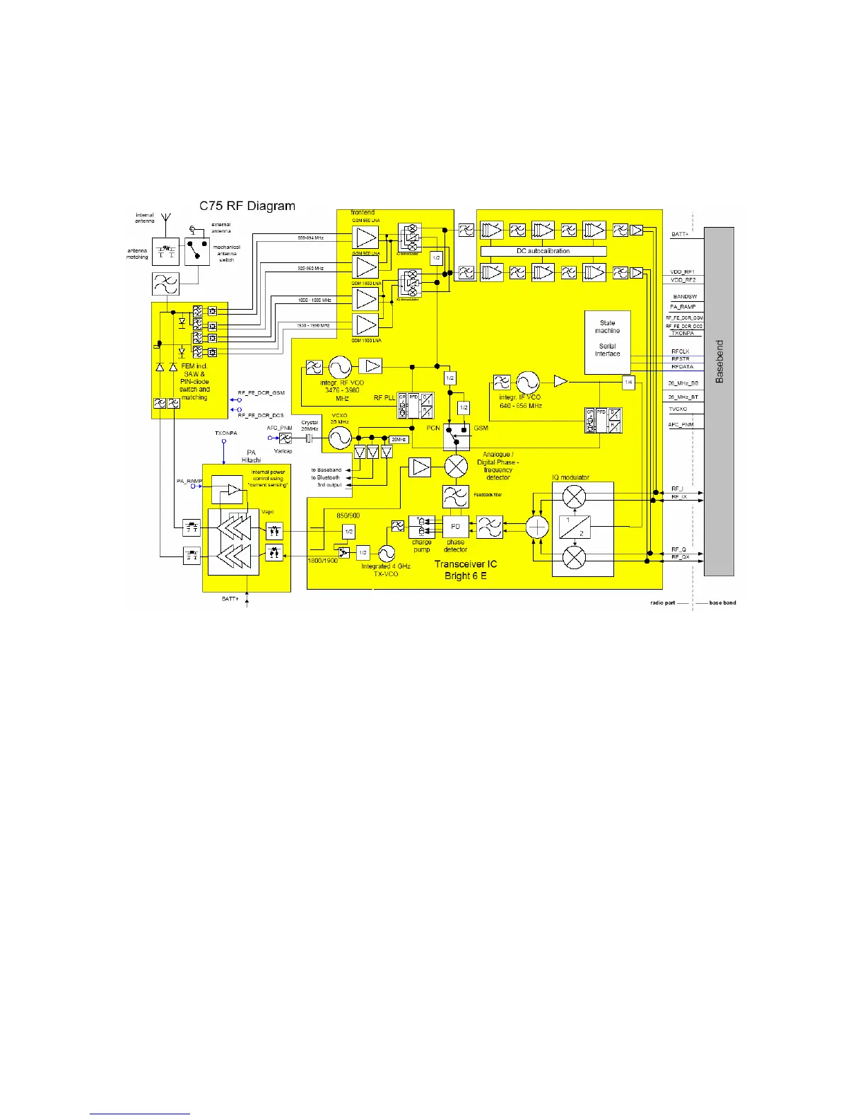
4.1 Block diagram RF part
4.2 Power Supply RF-Part
The voltage regulator for the RF-part is located inside the ASIC D1300. It generates the
required 2,8V “RF-Voltages” named VDD_RF1 and VDD_RF2. VDD_RF2 is passed via a 0Ω
resistor and renamed as VDD_BRIGHT as operating voltage for the BRIGHT. The voltage
regulator is activated as well as deactivated via VCXOEN_UC
(Functional F23) provided by the
SGOLDlite. The temporary deactivation is used to extend the stand by time.

 Loading...