Siemens Building Technologies, Inc. P84391-003B
8 Fernwood Road Sheet 1 of 4
Florham Park, New Jersey 07932
INSTALLATION INSTRUCTIONS
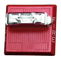
MULTI-CANDELA FOUR WIRE HORN STROBE APPLIANCES
(WALL MOUNT VERSION)
IMPORTANT
– All audible and visual signaling appliances must be
installed in accordance with all applicable national and local fire alarm
codes and any other required regulatory agencies.
Series HS-MC Multi-Candela Horn Strobe provides four selectable
candela settings (15, 30, 75, 110). The HS-MC allows for independent
operation of the strobe circuit and the horn circuit. It is the ideal choice
for retrofit applications as well as new installations. The HS-MC
appliance is UL Listed under Standard 1971 for Signaling Appliances
for the Hearing Impaired and UL Standard 464 for Audible Signal
Appliances. The HS-MC is also ULC Listed under Standard CAN/ULC-
S526-02 for Visual Signaling Appliances and Standard CAN/ULC-
S525-99 for Audible Signaling Appliances for Fire Alarm Systems. It is
listed for indoor use only
and can be mounted to double-gang, 4”
backbox, 100mm European backbox or MT-SUR-BOX surface
backbox (See wiring and mounting information). This appliance is
listed for wall mounting only
. The HS-MC appliance uses a xenon
flashtube with solid state circuitry enclosed in a polycarbonate lens to
provide maximum visibility and reliability for effective visible signaling.
Siemens Series HS appliances provide a selectable continuous or
Code 3 horn tone and non-synchronized strobe when connected
directly to a Fire Alarm Control Panel (FACP). They can also provide a
synchronized Code 3 (or March Time) horn tone and synchronized
strobe when connected to a notification appliance circuit running the
Siemens sync protocol. HS appliances can be field set for High (HI),
medium (MED) dBA or low (LO) dBA sound output. .
NOTE: The Code 3 temporal pattern (1/2 second on, 1/2 second off,
1/2 second on, 1/2 second off, 1/2 second on, 1-1/2 off and repeat) is
specified by ANSI and NFPA 72 for standard emergency evacuation
signaling. The Code 3 Horn should be used only for fire
evacuation signaling and not for any other purpose.
The HS-MC is designed for use with either filtered DC or unfiltered full-
wave-rectified (FWR) input voltage. All inputs are polarized for
compatibility with standard reverse polarity supervision of circuit wiring
by an FACP.
NOTE: All Canadian Installations should be in accordance with the
Canadian Standard for the Installation of Fire Alarm Systems –
CAN/ULC-S524-01 and Canadian Electrical Code, Part 1. Final
acceptance is subject to authorities having jurisdiction (AHJ).
NFPA 72/ANSI 117.1 conform to ADAAG Equivalent Facilitation
Guidelines in using fewer, higher intensity strobes within the same
protected area.
NOTE: Refer to P/N 315-096363 for the maximum number of
appliances on a single notification appliance circuit.
SPECIFICATIONS:
Table 1: UL/ULC Listed Models and Ratings
Model*
Operating Voltage (Special Application)
Per UL 1971
(VDC/VRMS)
Voltage Range Per
CAN/ULC-S526-02
(VDC/VRMS)
Strobe
Candela
(cd)
HS-MC 16.0-33.0 20.0-31.0 15/30/75/110
*Available in red and white.
Table 2: dBA Sound Output for 24VDC Models
Reverberant Per UL 464 Anechoic dBA @ 10 Ft. Per CAN/ULC-S525-99
Description
Volume
16.0VDC 24VDC 33.0VDC 20.0VDC 24VDC 31.0VDC
Low 80 83 86 88 90 91
Continuous Horn Medium 85 88 91 93 95 97
High 88 91 93 97 99 100
Low 75 79 82 88 90 91
Code 3 Horn or Medium 80 84 86 93 95 97
March Time** High 84 87 89 97 99 100
**Available in sync mode only.