10/11
Siemens Building Technologies CC1N7418en
HVAC Products 08.04.2004
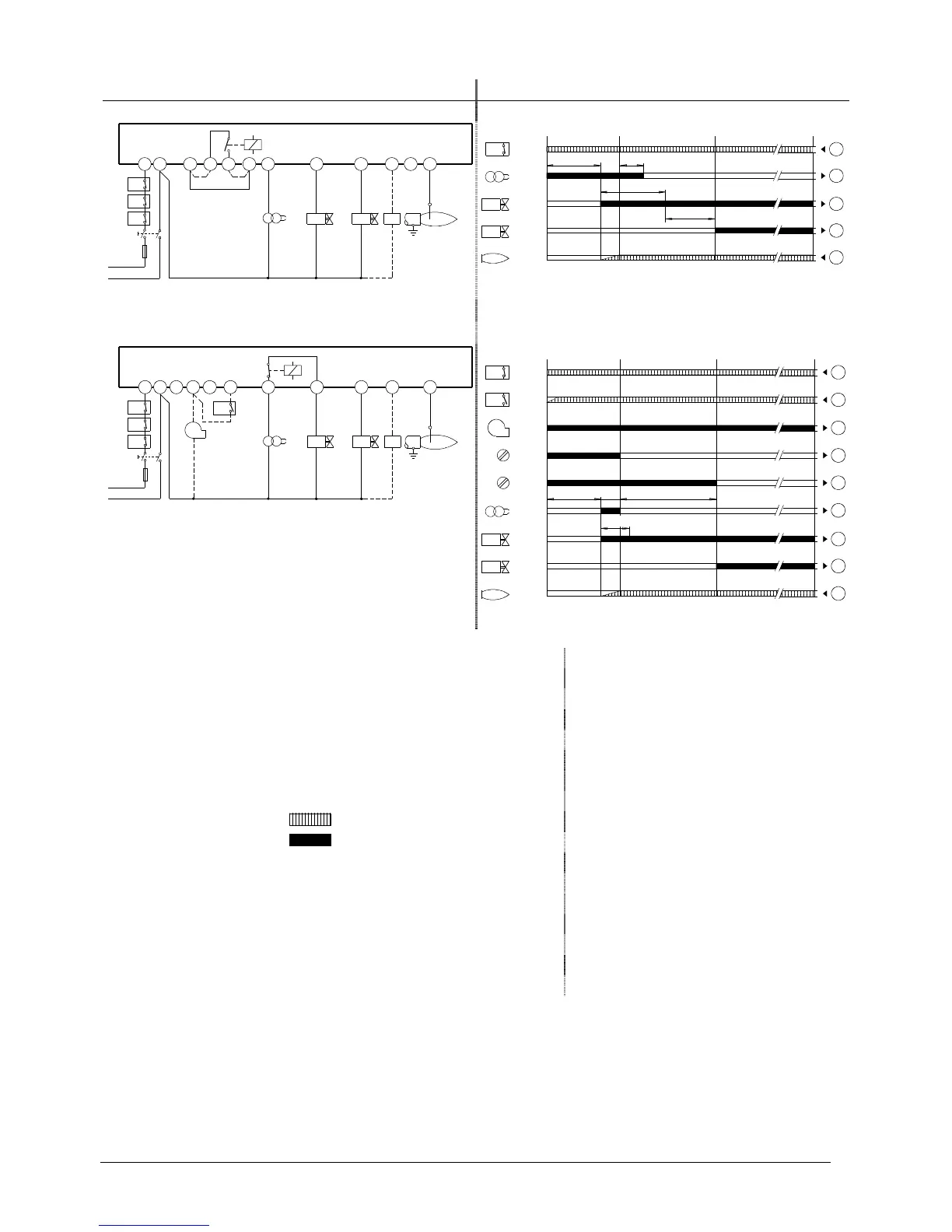
Connection diagram Control sequence
12
9
11
8
37 4 5 106
LGA41...
FR
W
R
L
N
Z
AL
ION
7418a04/0304
SB
BV1
BV2
12
Si
H
SB
R/W
Z
BV1
BV2
FS
1
7
4
5
12
t3
t3n
TSA
t4
A
B
C
D
7418f01/0200
12
689 11
7
4
510
12
LGA52... / 63...
SB
W
R
L
N
M
1)
LP
Z
AL
ION
BV1
BV2
FR
7418a05/0304
Si
H
SB
R/W
LP
M
9
6
Z
BV1
BV2
FS
t1 t3´
TSA
t4
1
11
8
9
6
7
4
5
12
AB
C
D
7418f02/0200
AL Fault status signal M Auxiliary fan
BV... Fuel valve R Thermostat or pressurestat
ION Ionization probe SB Safety limit thermostat
FR Flame relay Si External primary fuse
FS Flame signal W Limit thermostat
LP Air pressure switch Z Ignition transformer
H Main switch
Required input signals 1) Not monitored to EN 298
Burner control’s output signals
A Commencement of startup sequence C Operating position
B Time of flame establishment D Controlled shutdown by «R»
t1 Prepurge t3n Postignition
t3 Preignition time t4 Interval «BV1 – BV2»
t3´ Preignition time from the start of «TSA» TSA Ignition safety time
Legend
 Loading...