EasyManua.ls Logo

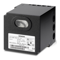
Siemens LGA52.150B17 User Manual

Siemens LGA52.150B17
15 pages
To Next Page IconTo Next Page
Page #1 background imageLoading...
Page #1 background image
CC1N7418en
21.06.2016
Building Technologies Division
7
418
Gas Burner Controls
LGA...
The gas burner controls are used for supervision, startup and control of
atmospheric gas burners of small to medium capacity without a fan in
intermittent operation.
The LGA... and this Data Sheet are intended for use by OEMs which integrate the
gas burner controls in their products.
Use, features
The LGA are designed for startup and supervision of atmospheric gas burners in
intermittent operation. The flame is supervised with an ionization probe.
Burner controls for gas burners and gas units with or without fan
to EN 298: 1994-02 or EN 298: 1993
Undervoltage detection
Air pressure supervision with functional check of the air pressure switch during
startup and operation
LGA41.173A27 and LGA52.171B27 are suitable for use with air heaters.
Note!
Do not use for new designs.
Note!
The following burner controls can be used for new designs:
LME1...
LME2...
LME3...
LME4...
General features
Special features

Other manuals for Siemens LGA52.150B17

Question and Answer IconNeed help?

Do you have a question about the Siemens LGA52.150B17 and is the answer not in the manual?

Siemens LGA52.150B17 Specifications

General IconGeneral
BrandSiemens
Product TypeController
ModelLGA52.150B17
Gas burnerYes
Oil burnerYes
Voltage220-240 V
Frequency50-60 Hz
Protection classIP40
ApplicationGas burner
Safety time3 seconds
Input Voltage220-240 V
Operating Temperature-20 to +60 °C

Summary

Gas Burner Controls Overview

Safety and Warning Notes

General Warning Notes

Crucial warnings to prevent injury, property damage, and environmental harm during operation.

Mounting and Installation Precautions

Essential guidelines for safe mounting and installation, including probe positioning.

Installation Procedures

General Installation Guidelines

Comprehensive instructions for wiring, grounding, and connecting components for safe installation.

Ionization Probe Electrical Connection

Commissioning and Safety Checks

Mandatory safety checks and their anticipated responses for proper system startup.

Technical Specifications

Flame Supervision Methods

Ionization Probe Supervision

Details on detector voltage, current, cable length, and insulation resistance.

Control Functions

Fault Handling and Reset

Fault Response Logic

Describes cause-and-effect for faults like erroneous flame signals or loss of flame.

Lockout and Reset Procedures

Details on lockout states, resetting the burner control after faults.

Internal Diagram LGA41

Internal Diagram LGA52/LGA63

Program Sequence Timing

Related product manuals