3
9. Reattach the terminal block by sliding it onto the
NCC-2F card edge and install the two screws. This
is a keyed connection and will only install one way.
10. After the NCC-2F is installed, install the NCC-2F
drivers following the instructions in the Driver
Installation section of this document.
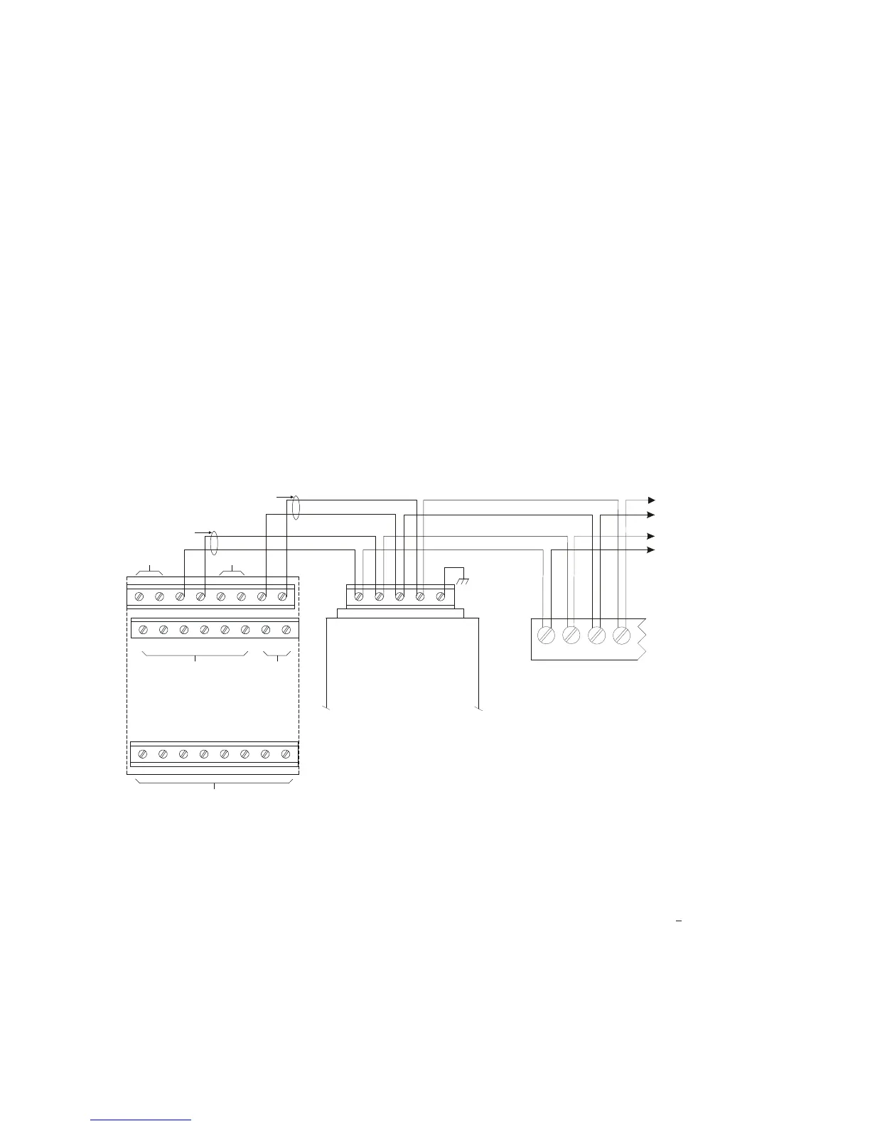
ELECTRICAL CONNECTIONS
Network (XNET)
The XNET connections are made on terminals 1-4 of the
terminal block on the rear of the NCC-2F. The primary
pair (or network A) is on terminals 1 and 2. The second-
ary pair (or network B) is on terminals 3 and 4.
For Style 4 networks, install a 120 ohm EOLR on ter-
minals 3 and 4. See Figure 4 for wiring details.
For Style 7 networks, connect to both the primary and
secondary pairs. See Figure 4 for wiring details.
Network (HNET)
The HNET connections are made on terminals 1-4 of the
terminal block on the rear of the second NCC-2F. The
primary pair (or network A) is on terminals 1 and 2. The
secondary pair (or network B) is on terminals 3 and 4.
Install a 120 ohm EOLR on terminals 1 and 2, and on
terminals 3 and 4.
For Style 4 networks, connect only the primary pairs.
See Figure 5 for wiring details.
For Style 7 networks, connect to both the primary and
secondary pairs. See Figure 5 for wiring details.
Network (HNET-VNT)
For Style 4 networks, connect only the primary pairs.
See Figure 6 for NCC-2F HNET-VNT connections.
For Style 7 networks, connect to both the primary and
secondary pairs. See Figure 6 for wiring details.
1 2 3 4 5 6 7 8
9 10 11 12 13 14 15 16
17 18 19 20 21 22 23 24
SEE NOTE 7
(MUST BE IN SAME ENCLOSURE AS THE PMI)
DO NOT USE
D
N
T
E
DO NOT USE DO NOT USE
ONE SLOT OF CC-5
NIC-C
1 2 3 4 5
PAI R A
SUPERVISED
POWER LIMITED
PAIR B
(OMIT FOR STYLE 4)
SUPERVISED
POWER LIMITED
LOCATED INSIDE NCC/
DESIGO CC/VNT
NOTE:
IF THE NCC/DESIGO CC/VNT
IS LOCATED AT THE END OF THE
XNET NETWORK, INSTALL EOLR
P/N 140-820350 ACROSS
TERMINALS 1 & 2 AND 3 & 4.
NCC-2F
MOM-4
TB3 OR TB4
NIM-1R / NIM-1W
1
2
3
4
TO ADDITIONAL
NIM-1Rs, NIM-1Ws,
NCC-2Fs OR NIC-C
Figure 4
NCC-2F XNET Connections
Refer to Wiring Specification for MXL, MXL-IQ
and MXLV Systems, P/N 315-092772 revision
6 or higher, for additional wiring information.
NOTES:
1. No EOLR required for NIC-C.
2. The screw terminals can accommodate one 12-24AWG or two 16-
24AWG.
3. From the NCC-2F to NIM-1R, NIM-1W or NCC-2F:
80 Ohms max. per pair.
Unshielded twisted pair - .5μF line to line
Shielded twisted pair - .3μF line to line, .4μF line to shield
4. From the NCC-2F to NIC-C:
2000 feet (33.8 ohms) max. per pair between CC-5s/CC-2s.
Unshielded twisted pair
.25μF max. line to line
Shielded twisted pair
.15μF max. line to line
.2μF max. line to shield
5. Use twisted pair or twisted shielded pair.
6. Terminate shields at one end only.
7. Power limited to NFPA 70 per NEC 760.
8. CC-5 terminals 9 - 14 are not connected and can be used to tie shields
together.
9. Positive or negative ground fault detected at
<10K ohms on pins 3-4,
7-8 of the NIC-C.
10. Each pair independently supervised.
11. Maximum voltage 8V P-P.
12. Maximum current 75mA during message transmission.
 Loading...