Siemens Industry, Inc.
Document No. 155-524P25
ET RAB-1
March 2, 2007
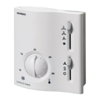
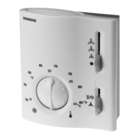
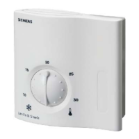
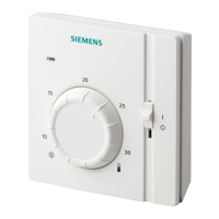
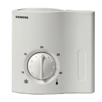
Thermostat with Manual
Changeover
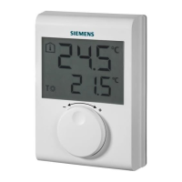
Description
Two-wire, gas diaphragm-based fan coil room thermostat with heating or cooling
sequence for two-pipe fan coil applications.
Features
• Manual, three-speed fan switch
• Dual setpoint temperature scale
• Fan release function
• Two-point control algorithm (On/Off)
• 24 to 120 Vac, 277 Vac operating voltage
• Manual changeover switch
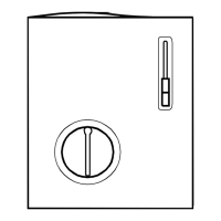
• Two mounting styles: electrical wall box or drywall
• Wall plate adapter (ARG70) included with electrical wall box mount styles
Application
Typically used in commercial, high-rise and light industrial buildings in conjunction with:
• Zone valves
• Thermal valves
• Fans
Product Numbers
See Table 1.
Technical Design
The RAB10... fan coil room thermostat is based on a two-wire, gas diaphragm
technology.
Operation
Heating Mode
When the heating mode is manually selected, and the room temperature falls below the
selected setpoint, the heating contact is closed.
Cooling Mode
When the cooling mode is manually selected, and the room temperature rises over the
selected setpoint, the cooling contact is closed.