3
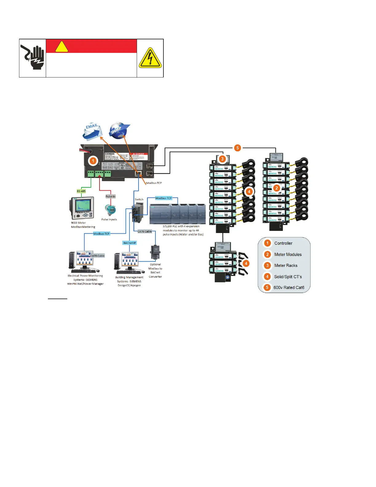
The SEM3 system is made up of the following
components and options:
1. Controller – The controller is used to communicate the
metered values to outside systems by way of a web page
interface, Modbus RTU or Modbus TCP. One controller can
manage up to 45 meter modules.
1)
The controller also has
the system digital inputs for receiving pulse inputs from
other metering devices as well as a digital output for the
combined KWh output of the system being metered.
2. Meter modules – There are two choices for the meter
modules that are differentiated by accuracy specication.
The accuracies are 1% for the standard accuracy modules
and 0.2% for the high accuracy modules. The accuracy is
tested in accordance to ANSI C12.20/0.2.
3. Meter racks – The meter modules are designed to snap into
the rack assemblies. The rack assemblies are sized by how
many modules will t into each and come in 3, 9, 15 and 21
module congurations.
4. CT or current transformers – The SEM3 systems has solid
core CTs for use with the system in the following maximum
amperage ranges 50, 125, 250, 400, 600, 800 and 1200
amps. These are maximum amperage ranges for normal
usage but will measure accurately down to 1% of the
maximum range.
5. Communication cables – The communication cables
are designed like CAT 5 cables but are insulated for use
in systems up to 600 volts. The cables are for two way
communication from the controller to the rack/meter
modules.
Figure 1 SEM3 System
SEM3 System
!
DANGER
Hazardous Voltage.
Will cause death or serious injury.
Turn off and lock out all power before working on
this equipment.