Do you have a question about the Siemens SEM3 and is the answer not in the manual?
Crucial safety warning regarding hazardous voltage and required precautions.
Guidelines for qualified personnel, electrical codes, and environmental operating conditions.
Details on input protection, conductor sizing, and terminal torque specifications.
Requirements for emergency disconnects and proper installation of Current Transformers (CTs).
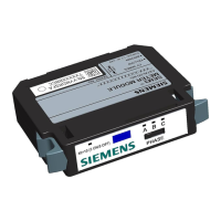
Visual representation and description of the SEM3 system's controller, modules, racks, CTs, and cables.
Steps for configuring the controller, assigning static IP addresses, and verifying network connection.
Instructions on setting up meter modules and configuring CT ratios via the controller.
Explains rack configurations and how to assign addresses using dip/rotary switches.
Details the address ranges for meter modules based on rack type and switch settings.
Covers default login, user roles, and system configuration options like IP and refresh intervals.
Customization of meters, viewing real-time data, and system diagnostics.
The Siemens SEM3™ - Embedded Micro Metering Module™ is a comprehensive system designed for energy management functions, providing detailed metering capabilities and system control. It is suitable for a wide range of applications, from single-phase monitoring to multi-pole circuit breaker configurations.
The SEM3 metering system consists of a controller, meter modules, meter racks, and current transformers (CTs). The controller acts as the central interface for system setup, managing system settings, CT and PT ratios, alarm settings, communications settings, and passwords via a web page interface. Meter modules are single-phase meters that connect to appropriately sized CTs and snap into meter racks. These racks have hard-coded module addresses for communication with the controller. The system supports various configurations, including multi-pole circuit breakers, where meter modules must be mounted contiguously. The controller gathers data from the meter modules, which measure energy consumption, and provides real-time data, alarm status, and historical information. The system can integrate with supervisory systems like WinPM.Net, Power Manager, and SCADA/Building Management Systems using Modbus protocol.
| Brand | Siemens |
|---|---|
| Model | SEM3 |
| Category | Transformer |
| Language | English |