Replacement Of The
Main Logic Board
NOTE
Aftermaking sure no voltage is present,take the following steps:
Before you disconnect the control wires from the Logic Board terminal strip,make sure you
record the wire markernumbers and locations.Reconnect these wires to the same terminals
on the new board.This board is held with one screw and grooves in the card guide.
1 Remove the fourscrews holding the coverplate.
2 Remove the coverplate.
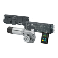
3 The Logic Board to be replaced is on the right; it is the board with the
adjustment potentiometers and LED light.
4 Remove the screw holding the Logic Board in place.
5 Slowly slide the board out of the unit to a point where you can see the red
wires that are attached to the board with push-on terminals.These wires power
the fan.Disconnect these wires,tagging them,so that they will go on the
same terminals on the new board.
6 Disconnect the ribbon connectorfrom the board,noting which receptacle it
came from so that you can replace it in the same receptacle on the new board.
7 Slide the new board part of the way into the grooves of the card guide.The
board must be correctly placed into the appropriate groove.
8 Connect the tagged red wires to theirappropriate terminals on the board.
9 Afterconnecting the red wires,continue to slide the board until it bottoms out.
10 Reconnect the ribbon to the terminal - make sure it is firmly in place.(Some
models will have three ribbon connectors.)
11 Reconnect the control wires to the correct position on the terminal strip.
12 Secure the board with the holding screw.
13 Replace the coverbefore energizing controller.
14 Re-energize the controller.
Tel: ++49 (0) 9131-7-43833 (8°°-17°° MEZ) Fax: ++49 (0) 9131-7-42899
E-mail: NST.technical-support@erl17.siemens.de Internet: www
.ad.siemens.de/support
Technical Support:
Subject to change without priornotice.
QL
Siemens AG 1999
OrderNo.:3ZX1012-0RW34-3AN1
Printed in the United States
 Loading...