EasyManua.ls Logo

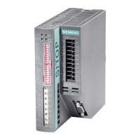
Siemens SITOP DC UPS 6EP1931-2FC21 User Manual

Siemens SITOP DC UPS 6EP1931-2FC21
18 pages
To Next Page IconTo Next Page
Page #1 background imageLoading...
Page #1 background image
© Siemens AG, 2009 1/18
Considerations for Use
of the SITOP DC UPS Module
6A without interface (6EP1931-2DC21)
6A with serial interface (6EP1931-2DC31)
6A with USB interface (6EP1931-2DC42)
15A without interface (6EP1931-2EC21)
15A with serial interface (6EP1931-2EC31)
15A with USB interface (6EP1931-2EC42)
40A without interface (6EP1931-2FC21)
40A with USB interface (6EP1931-2FC42)
500S (15A / 2.5kWs capacitor) (6EP1933-2EC41)
500S (15A / 5kWs capacitor) (6EP1933-2EC51)
500P (15A / 5kWs capacitor) (6EP1933-2NC01)
500P (15A / 10kWs capacitor) (6EP1933-2NC11)
Release 2
Question and Answer IconNeed help?

Do you have a question about the Siemens SITOP DC UPS 6EP1931-2FC21 and is the answer not in the manual?

Siemens SITOP DC UPS 6EP1931-2FC21 Specifications

General IconGeneral
Input Voltage24 V DC
Input Voltage Range19.2 - 30 V DC
Output Voltage24 V DC
Output Current10 A
Power240 W
Protection ClassIP20
Battery TypeLead-acid
Interfacespotential-free relay contact
Storage Temperature-20 to +70 °C

Summary

SITOP DC UPS Module Introduction

Overview of SITOP DC UPS Module

General overview of the SITOP DC UPS module and its applications.

SITOP DC UPS Module Core Functions

Normal Operation Mode Explained

Describes the UPS functioning when the input voltage is stable and sufficient.

Buffer Operation Mode Explained

Explains how the UPS operates using battery power when input voltage fails.

SITOP DC UPS Module Configuration Settings

Setting the Cut-in Threshold Voltage

Configuration of the input voltage level that triggers battery backup.

Battery Charging Parameter Settings

Setting battery charging parameters, including end-of-charge voltage and current.

Buffering Time and Output Disconnection Configuration

Configuration of backup duration and output voltage disconnection after buffering.

Operating State and Compatibility Settings

Setting the module's ON/OFF state and compatibility with different UPS families.

SITOP DC UPS Module Status Monitoring and Alarms

Signaling Indicators for Operation Modes

Explanation of LEDs and relay contacts for normal, full charge, and buffer modes.

Troubleshooting with Alarm Messages

Details on alarm signals for lack of buffer readiness and battery change requirements.

SITOP DC UPS Module PC Communication Interface

Serial and USB Interface Design

Describes serial and USB interface hardware and connection methods.

Data Transmission and Reception via PC

Covers transmitting UPS status data and receiving remote signals via PC.

SITOP DC UPS Module Detailed Operating Modes

Power Failures Without Communication Interface

Behavior during long and brief power failures when no communication interface is used.

Power Failures With Communication Interface

Behavior during long and brief power failures when a communication interface is used.

SITOP DC UPS Battery Module Management

Guide to Battery Module Selection

Table and instructions for choosing the correct battery module for the application.

Understanding Battery Discharge Characteristics

Graphical representation of battery voltage drop under various discharge currents.

Calculating Required Battery Capacity

Guidance on calculating required battery capacity using characteristic fields.

Related product manuals