Installation Instructions
Document No. 129-319
September 30, 2009
Wireless TEC Transceiver (TTX)
Item Number 129-319, Rev.CA Page 1 of 2
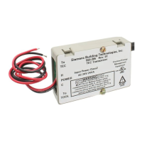
Product Description
The Wireless Terminal Equipment Controller (TEC)
Transceiver (TTX) communicates with the Wireless
Room Temperature Sensor (RTS) and uses radio
frequency hopping technology. The TTX surface
mounts near the TEC via a bracket.
Product Numbers
550-205 TEC Transceiver, mounting bracket and
hardware, two power connectors, and
RJ11 to RJ11 communications cable
Accessories
540-143 Laptop cable (RJ11 to DB9)
550-200 Replacement communications cable
(RJ11 to RJ11)
550-710 Isolation transformer, 1:1,
(24V in; 24V out) *
550-074 Fitting for optionally mounting
antenna through a knockout (5 pack)
NOTE: 3M Scotchlok™ power connectors are
available from W.W. Grainger, Inc. (part
number 4YT73) via the Field Purchasing
Guide.
* When TTX/TEC is powered off a main
transformer that is different from the field panel
main transformer, then a ground loop could
potentially occur and necessitate the user of an
isolation transformer for the TTX.
Related Products
550-660 * Wireless TEC Room Temperature
Sensor (RTS)
544-790 * Sensor base plate
544-643 RTS passkey (for demo,
commissioning, and service mode)
* Add letter suffix to indicate desired color:
A = Desert Beige, B = White (e.g., 544-790B).
Expected Installation Time
38 minutes
Required Tools
• Lineman’s pliers
• No. 2 Phillips screwdriver
NOTE: Depending on the actual installation, some
of these tools may not be required.
Prerequisites
FCC NOTE: FCC ID MQX550205—001 Grantee
Code 123—Equipment Product Code
This device complies with part 15 of the FCC Rules.
Operation is subject to the following two conditions:
(1) This device may not cause harmful interference,
and (2) this device must accept any interference
received, including interference that may cause
undesired operation.
UL Listed: UL 916 PAZX
Industrie Canada certification:
TTX (550205): CANADA 3606104672
NOTE: The manufacturer is not responsible for any
radio or TV interference caused by
unauthorized modifications to this equipment.
Such modifications could void the user’s
authority to operate the equipment.
Installation
Mounting the Bracket
1. Mount TTX Bracket on a surface near the TEC
(Figure 1). Position the bracket so that the TTX
communications line and power line can
adequately reach the connections at the TEC.
NOTES:
1. The TTX antenna base is articulated with stops
at 45° increments to facilitate installation. During
TTX installation, point the antenna towards the
space where the RTS is located to minimize any
obstruction in communications.
2. The broadcast direction of the antenna is
spherical.