3/8
Building Technologies Network Node WTT16…, WTX16… CE1N2874en
HVAC Products 14.07.2005
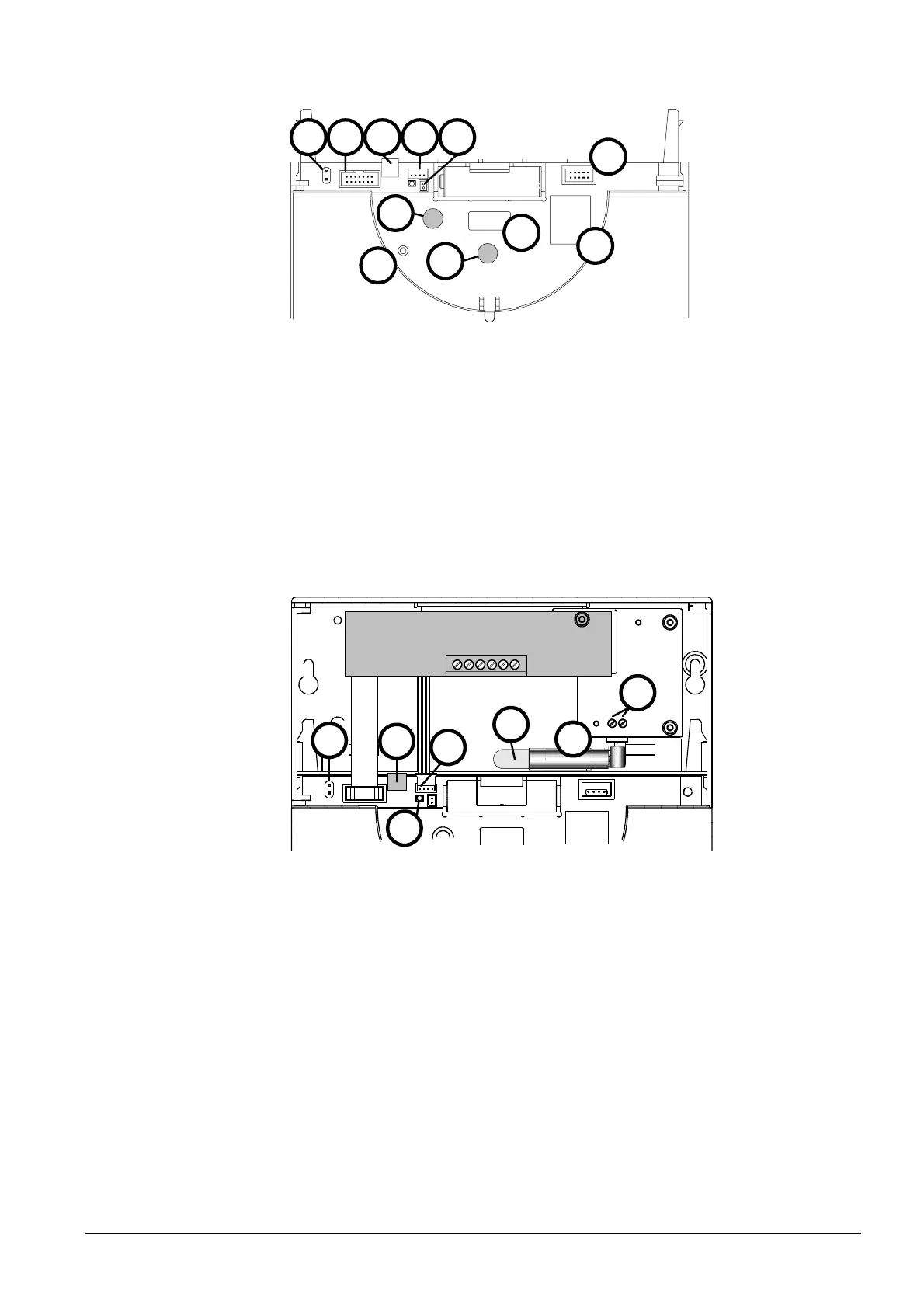
The housing with the electronics is identical for all types of network nodes. It contains
the network controls:
RESET
MODE
DISPLAY
1 2 3 4
6
7
11
10
8
9
5
1 Connector for M-bus service connection
2 Connector for enhancements
3 Screw terminal for the fixed M-bus connection
4 Connector for power supply DC 3,6 V
5 Connector for backup battery Indication of mains supply
6 Operating mode button (red)
7 Button for switching the display (blue)
8 Reset button (recessed)
9 Display
10 Connector (not for the user)
11 Firmware memory (covered up)
The wall-mounted section of the network nodes WTT16… contains only the main battery.
The wall-mounted section of the network nodes WTX16 and WTX16.232 contains the
power pack and possibly an additional RS232 interface.
GND
n.c.
RTS
CTS
Rx
Tx
4
2
7
3
5
6
1
1 Mains connection L and N
2 Preinstalled mains cable (no flexible power cable!)
3 Extra insulation (shrink sleeve)
4 Connector for power supply DC 3,6 V
5 Screw terminal for the fixed M-bus connection
6 Connector for M-bus service connection
7 Indication of mains supply
Electronics section
Wall-mounted section
 Loading...