.
22. Re-install the engine mounts, bolt the engine in place, then install the pushrod connector (included in your kit) on your
engine's carburettor control arm. Locate and mark the best spot on the firewall for the throttle pushrod to exit and line up
with the pushrod connector. Now you can remove the engine and mounts, and drill at the mark with a 9/64" drill bit.
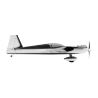
23.
a. Hold the two 3/32" die-cut balsa fuselage sides together and sand the edges lightly until they are a perfect match.
b. Mark the positions of the three formers on the fuselage-sides. Marking the right-hand fuselage side is easy. Place it
over the "Typical Radio and Engine Installation" drawing on the plan and use the small guidelines to mark the balsa.
Now you can use the right-hand fuselage side to transfer identical markings to the inner surface of the left-hand
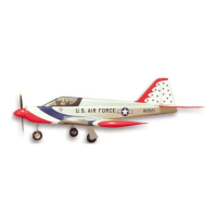
24.
a. Glue the 3/32" die-cut balsa fuselage doublers to the fuselage sides.
b. Glue a piece of 1/4" balsa triangle along the bottom of each fuselage side. Notice that the aft end of the triangle
piece should end at the rear face of former F-4.
c. Tack glue the 1/8" die-cut lite-ply formers F-3 and F-4 in place on one of the fuselage sides using a triangle to make
certain they are square with the side.
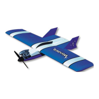
25.
While holding the second fuselage side in place on the formers, check the alignment of the fuselage over the top view on
the plan. When satisfied, glue both fuselage sides firmly to F
26.
a. Tape former F-1 in place on the front of the fuselage, and again check the alignment over the top view on the plans.
Notice that the correct amount of downthrust (4 deg.) is built in automatically by lining up the front face of F-1 with
the front edge of the fuselage sides. There should be no side thrust when viewed from above. When satisfied, glue
F-1 to the fuselage sides from the front and back with thin CA.
b. Trim the 1/4" triangle stock flush with the front of F-1.
c. Cut two braces for F-
1 from 1/4" balsa triangle stock and notch them as necessary to clear the blind nuts on the back
of F-1. Apply slow CA to the braces and press them firmly in place.
d.
It may be necessary to redrill the hole for the throttle pushrod through a triangle brace that was installed. Use a 9/64"
27.
Carefully position a straightedge so that it's lined up with the rear face of F-4 on the outside of the fuselage. Use a sharp
knife to cut through about half the thickness of each fuselage side. Now the back end of the fuselage can be literally
"cracked" into position. If it happens to snap off completely, that's okay; it can be re
attached in the next step.
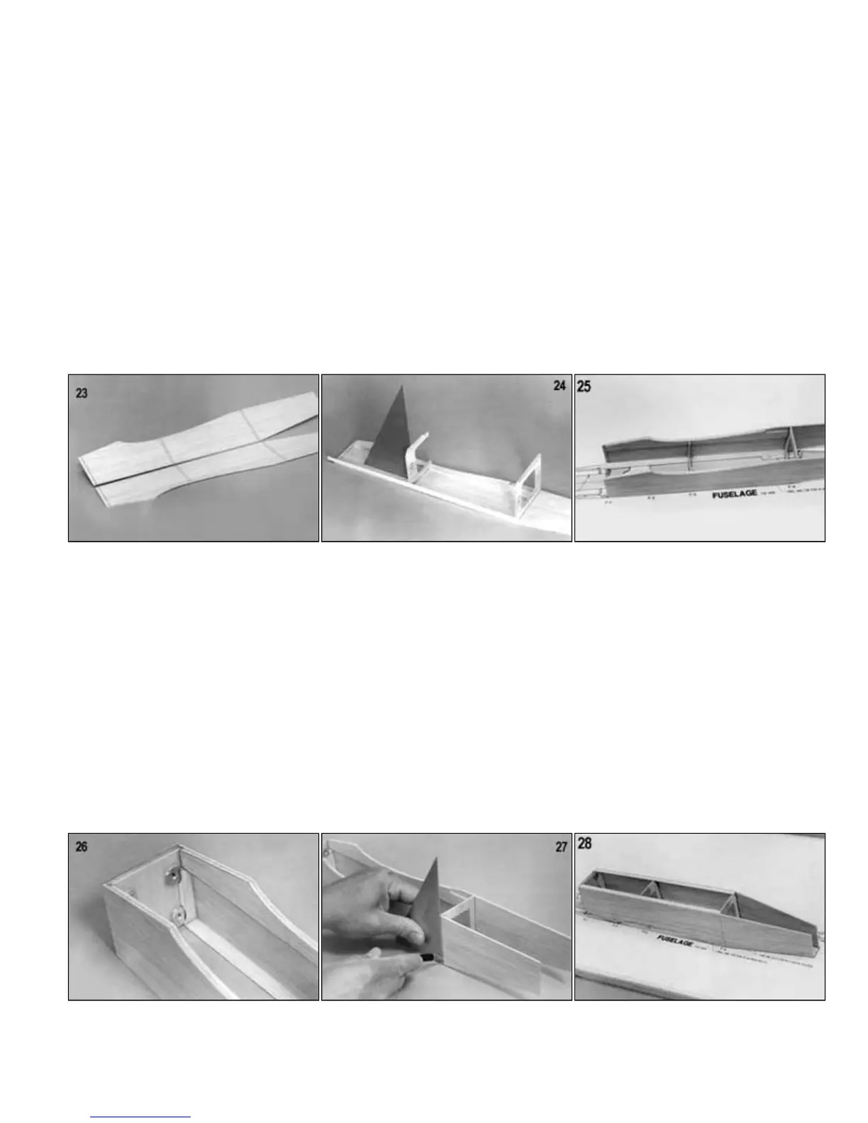
28.
Firmly pin the fuselage upside down over the top view on the plan so that it can't move. Now you can hit the cracked joint on
each side with a bit of CA to hold the rear fuselage in alignment.