Fig 5
Fig 6
Fig 7
Fig 8
Fig 9
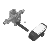
QThe valve body is equipped with service stop valves. Close the hot
and cold water supplies.
QPay close attention to location setting of the mechanical stops (5
and 6). The thick mechanical stop (5) regulates cold temperature,
while the thin top mechanical stop (6) regulates the hot tempera-
ture.
QRemove the mechanical stops, which are below the cap nut in the
center of the valve.
QLoosen the four corner screws (6) and remove the valve cover (7)
with the O-ring (7). The cartridge assembly is now exposed.
QPull the cartridge out. Do not damage the O-ring seals.
QReverse the cartridge 180
o
by turning it upside down. Place it
into the valve body. Two alignment pins located on the rear of
the cartridge must sit in the locating holes within the valve body.
Notice position of hot ("H") and cold ("C") markings on the cartridge
to assure the correct reversal in relation to the back-to-back installa-
tion.
QPut the O-ring on the valve cover. Make sure the surface of the
valve cover, on which the O-ring will sit, and the O-ring are both
clean.
QPosition the valve cover with stop pin facing down. Seat the
cover to the body. Do not pinch the O-ring. The assembly should t
together with a minimum of pressing force.
QTighten up the cover screws, rst lightly and diagonally, and then
more rmly.
QClose the valve by turning the cartridge stem clockwise. Position
the mechanical stops as shown in gure 6 over the cartridge stem
and push it into place. Thread on the cap nut and the stem exten-
sion with All Thread; then you are ready for the trim.
Mechanical
Stops
Stop Pin
2
Stops
Mechanical
Stops
Valve Cover
O-Ring
Cartridge
Assembly
Mud Guard
Tempress II Pressure Balance Valve
Cartridge Replacement Instructions
SigmaFaucetParts.com
Fig 5
Fig 6
Fig 7
Fig 8
Fig 9
QThe valve body is equipped with service stop valves. Close the hot
and cold water supplies.
QPay close attention to location setting of the mechanical stops (5
and 6). The thick mechanical stop (5) regulates cold temperature,
while the thin top mechanical stop (6) regulates the hot tempera-
ture.
QRemove the mechanical stops, which are below the cap nut in the
center of the valve.
QLoosen the four corner screws (6) and remove the valve cover (7)
with the O-ring (7). The cartridge assembly is now exposed.
QPull the cartridge out. Do not damage the O-ring seals.
QReverse the cartridge 180
o
by turning it upside down. Place it
into the valve body. Two alignment pins located on the rear of
the cartridge must sit in the locating holes within the valve body.
Notice position of hot ("H") and cold ("C") markings on the cartridge
to assure the correct reversal in relation to the back-to-back installa-
tion.
QPut the O-ring on the valve cover. Make sure the surface of the
valve cover, on which the O-ring will sit, and the O-ring are both
clean.
QPosition the valve cover with stop pin facing down. Seat the
cover to the body. Do not pinch the O-ring. The assembly should t
together with a minimum of pressing force.
QTighten up the cover screws, rst lightly and diagonally, and then
more rmly.
QClose the valve by turning the cartridge stem clockwise. Position
the mechanical stops as shown in gure 6 over the cartridge stem
and push it into place. Thread on the cap nut and the stem exten-
sion with All Thread; then you are ready for the trim.
Mechanical
Stops
Stop Pin
2
Stops
Mechanical
Stops
Valve Cover
O-Ring
Cartridge
Assembly
Mud Guard
Phone!800-280-4053