EasyManua.ls Logo

Signet Pulse 2.200 LS User Manual

Signet Pulse 2.200 LS
12 pages
To Next Page IconTo Next Page
Page #1 background imageLoading...
Page #1 background image
Page 1 of 12 DocNo.DCP0001326 DSM 06/01/05 rev7
Features
The P2.200 LS amplifier contains two identical independent amplifier modules. Each has one Main and one
Aux. input. Routing logic allows the Main and Aux. to mix; this allows the monitoring tone to pass at all times
and the monitoring system to operate. If the PTT is operated, the Main input overrides the Aux.
Each modules status is displayed on the front panel along with an output level bar graph and status
indicators. All sections of the amplifier and charger are constantly monitored for faults or abnormal operation:
1 The load monitoring checks the power absorbed by the loudspeaker load at 22 kHz and compares this
with the threshold and window levels set at installation. If the power drawn deviates outside the window a
fault is indicated on the front and rear of the unit and signalled to other equipment via the relevant fault
outputs.
2 If the impedance monitoring tone is not being received by the amplifier, both the Load Hi and Load Low
front LEDs light and the rear Tone Fail light shows.
3 Should either leg of the loudspeaker wiring short to system earth this will also light the Load Hi and Load
Low LEDs on the front panel, along with the Earth Fault LED on the rear.
4 Mains power status is also monitored, along with the internal fuses, to give a complete picture of the state
of the amplifier.
The load monitoring system also provides an output to drive a hot swap automatic amplifier replacement
system, via the HSP port, on failure of the amplifier only. Should a load fail short or open circuit but the
amplifier is still OK, the hot swap output will not operate. This means that any loudspeakers that can be
driven will operate and leaves the hot swap amplifier available for use on another potential failure.
The output from each module is presented on a three-way socket and is fully floating. The standard output
voltages are 50V and 100V, allowing two modules to be connected in series to give 400W at 100V line.
The power supply has a 24 Vd.c. battery input and an onboard battery charger.
Technical Description
Amplifier Modules
The Aux. and Main line level inputs are de-balanced and pass via level controllers and an analogue switch
into a summing amplifier where they are mixed. If the contact input is asserted (470 ohms to ground) a logic
circuit disconnects the aux. input.
The protect circuit disconnects the output transformer when the voltage rails fall below 22 Volts, exceed 36
Volts, or when a d.c. offset is present on the output rails. The signal then passes through to the output stage,
which is a feed-forward current-mode bridge circuit and the output level meter monitors the level at this stage.
The output current is passed through the primary of the output transformer and through a low value output-
sensing resistor. The output of the transformer is tapped at 50 and 100 Volts. If the 50 Volt taps are
connected in series the unit provides a single 400 Watt output at 100 V line.
Power Supply
A large capacitor reservoir provides a very smooth output, even under large current surges. Two separate
internal 10 Amp fused outputs connect to the two amplifier modules.
A separate low-current feed passes via the sleep enable selector link into the sleep timer section. Another
feed passes, via the Aux. on LED (this shows that the Aux. power is available on the rear connector) through
a 3 Amp fuse to the Aux. power connector. With mains voltage operation this unregulated output is at
approximately 32 Vd.c. When mains has failed, this output is connected to the battery and therefore operates
at battery voltage level.
A 27.6 Volt regulator is also taken off this line and used to charge external batteries via a 20 Amp fuse.
PSU and amplifier faults are returned into the monitoring circuit from both amplifiers, slugged to prevent false
faults being reported externally, and passed to the open collector fault outputs on the SIP port. A fourth open
collector output is normally set as OK (normally closed) and opens when any fault occurs.
Operation Instruction Manual
Pulse 2.200 LS Dual 200W 100V line Amplifier with Monitoring
Question and Answer IconNeed help?

Do you have a question about the Signet Pulse 2.200 LS and is the answer not in the manual?

Signet Pulse 2.200 LS Specifications

General IconGeneral
BrandSignet
ModelPulse 2.200 LS
CategoryAmplifier
LanguageEnglish

Summary

Features

Technical Description

Amplifier Modules

Describes the line level inputs, summing amplifier, and protect circuit of the amplifier modules.

Power Supply

Details the capacitor reservoir, fused outputs, sleep timer, auxiliary power, and battery charging circuit.

Front Panel Indicators

Amplifier Module Indicators

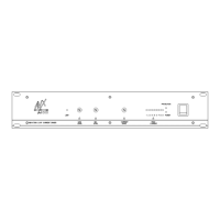
Lists and describes status indicators for each amplifier module, e.g., Output level, Protect, Sleep, Load Hi/Low.

Power Supply Indicators

Lists and describes status indicators for the power supply unit, e.g., AC in, DC in, PSU Fault, Aux. on, OK.

Rear Panel Controls and Features

Rear Panel Connectors and Controls

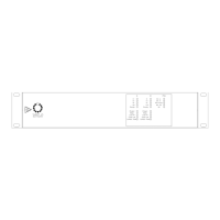
Identifies and describes rear panel connectors and controls like AC Input, Battery Input, SIP Port, Aux. Power, and Audio inputs.

Installation

Unpacking and Placement

Instructions for unpacking, inspecting for damage, and recommended placement of the amplifier.

AC Power Operation

Guidelines for connecting AC power, mentioning inrush current and the need for a soft start device.

DC Power Operation and Battery Calculation

Quiescent and Alarm Battery Capacity

Calculates required battery capacity for quiescent and alarm states, including de-rating.

Ancillary Equipment Battery Needs

Details additional battery capacity needed for ancillary equipment and aging factors.

Power-up Sequence

Specifies the correct order for connecting power and battery supplies to prevent damage.

Fault Monitoring

PTT Monitoring

Explains how the PTT input is monitored using a resistive potential divider and fault detection.

Loudspeaker Circuit Monitoring

Covers monitoring of loudspeaker lines for continuity, impedance, and earth faults, including EOL units.

Fault Output Ports

Describes the SIP port and Hot Swap ports for reporting faults, including slugging and detailed fault information.

Input Connections

Connecting to SigNET IX LS

Diagram and notes for connecting the P2.200 to a SigNET IX LS prioritised mixer with battery backup.

Connecting to SigNET SS2n

Diagrams showing connections to a SigNET SS2n network station for both amplifier modules or a single module.

Connecting to Integrity Mainframe

Diagram illustrating the connection of the P2.200 to an Integrity Mainframe.

Output Connections and System Setup

100 Volt Output Configuration

Explains using the amplifier with 100V constant voltage systems and the need for line matching transformers.

Operation and Set-up Procedure

Steps for verifying audio input, monitoring tone, setting output levels, and configuring load monitoring.

Internal Adjustments

Mix/Mute and Sleep Mode Settings

Configuration of Mix/Mute for monitoring tone and disabling Sleep Mode for life safety compliance.

PSU Monitor and SIP Port Configuration

Settings for battery monitoring and how the SIP port outputs are wired for Node A or Node B designation.

Specifications

Amplifier Performance Specification

Details sensitivity, impedance, CMRR, output power, frequency response, THD, SINAD, and protection features.

Physical and Power Supply Specification

Covers physical dimensions, material, weight, AC/DC input, charging voltage/current, and monitoring current.

Monitoring and Fuses

Specifies detection frequency, type, window/sensitivity settings, EOL units, and a list of all fuses used in the unit.

Related product manuals