12
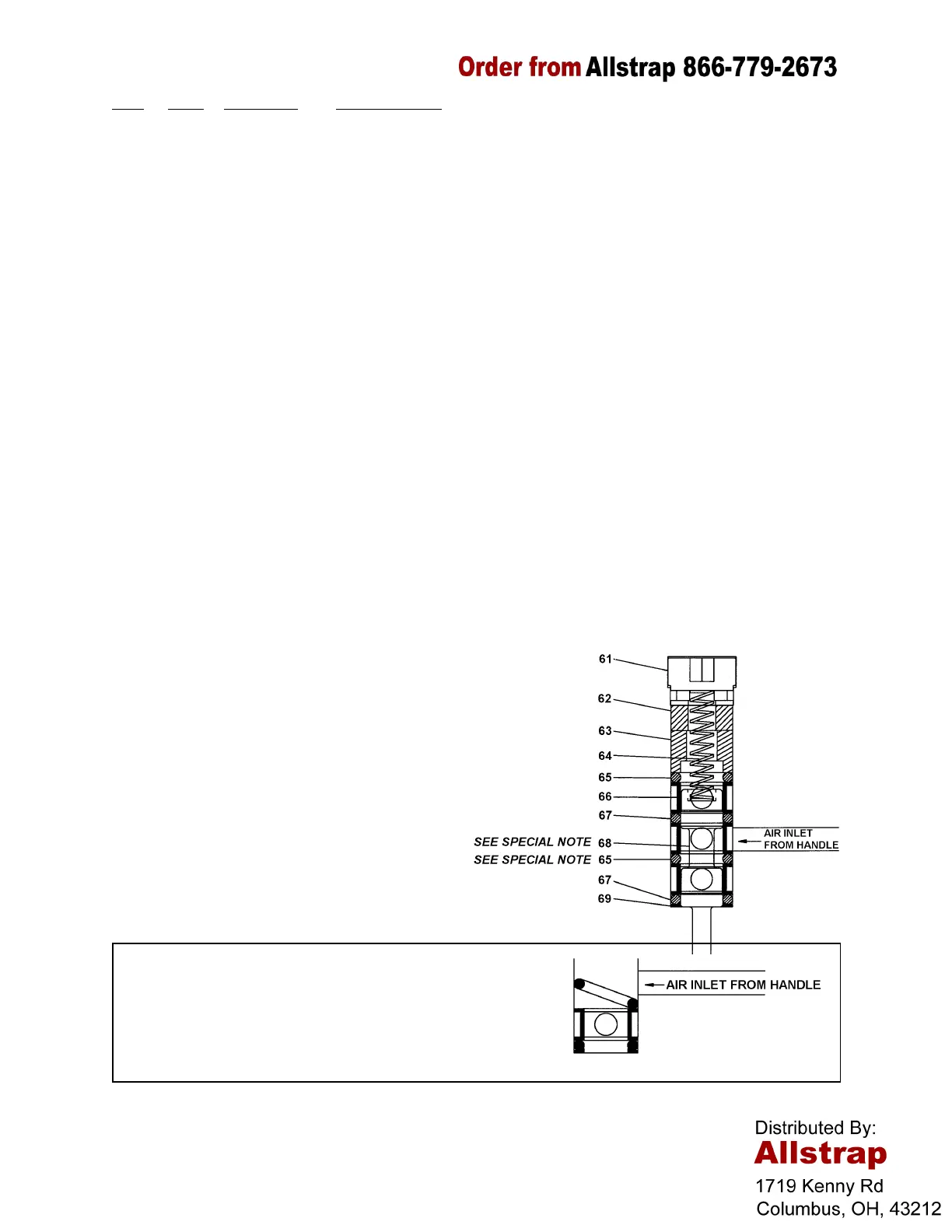
PARTS LIST, CYLINDER ASSEMBLY
KEY QTY. PART NO. DESCRIPTION
1 1 424137 Mounting plate
51 1 424139 Cylinder
52 1 008672 Bushing
53 1 286373 Info sign (3 icon)
54 1 424210 Warning sign
55 1 424207 Trigger pin
56 2 180131 SHSS, M4X 8
57 1 424145 Trigger
58 1 008478 Reducing bushing
59 1 020704 Hansen plug
60 1 424216 Tag
61 1 424141 Valve plug
62 1 424206 Compression spacer
63 1 424205 Sleeve spacer
64 1 093839 Compression spring, LEE #LC038-16MW
65 2 020680 O-Ring #112
66 3 023040 Valve sleeve
67 2 008596 O-Ring #111
68 1 424208 Valve stem
69 1 424204 Bottom spacer
70 1 424142 Boot clamp
71 1 424143 Nameplate (114)
1 424201 Nameplate (34)
72 4 002187 Lock washer, 1/4
73 4 280832 SHCS, M6 X 30, full thread
74 1 180900 Information sign
! Standard hardware parts may be obtained from local hardware suppliers.
! When ordering parts, please show tool model, part number, and name.
! Recommended spare parts are underlined and should be stocked.
! This tool has metric fasteners.
NOTES:
1. Bottom spacer (69) must be installed
with “lip” facing up.
2. O-rings (65 & 67) are different sizes and
must be installed in the proper
sequence.
3. The (2) o-rings (65) are larger than the
bore diameter and will not sit flat until
the subsequent spacer in pushed into
place.
4. Lubricate all O-Rings with White
(Lubriplate) grease, GR-132, Part No
422792.
5. Torque the four cap screws (Key 73) to
65-75 in lbs. (7.2-8.5Nm).
SPECIAL NOTE:
The lower of the two large o-rings (65) must be placed so
the portion of the o-ring closest to the handle air inlet is
below the inlet when the valve sleeve (68) is pushed into
place. Failure to do this could result in air leakage.
 Loading...