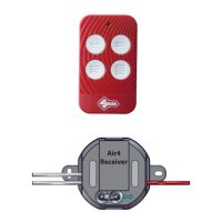
Air4 Universal Receiver
Copyright Silca S.p.A 2020. All right reserved
3
English
AIR4 UNIVERSAL RECEIVER
OPERATING PARTS
P
S
B
C
A
G
H
F
CH2
CH1
FIG.1
A. Aerial
Note: Make sure the receiver antenna wire is not twisted and/or bent; to ensure the best signal it must be as
straight as possible.
B. LED L1
C. LED L2
P. Buon P
S. Buon S
F. 12/24V AC/DC power supply terminal.
Note: The Air4 Universal Receiver power supply terminals are without polarity; the power supply (+) can be con-
nected to either terminals, at the user’s discreon.
G. Normally open relay contact RELAY 2 (CH2)
H. Normally open relay contact RELAY 1 (CH1)
Air4 Universal Receiver Technical Data
Power supply: 12 VAC/DC to 24 VAC/DC
Relay contacts: 3A-250VAC / 3A-30VDC
Frequency : 433,92MHz
Maximum number of buons memorisable: 280
The power source must comply with the limits of class 1 (ES1) and class 2 (PS2) power sources accor-
ding to the EN 62368-1 standard.