S
samuel57Aug 16, 2025
What does 'TROUBLE LINE 1' mean on SILENT KNIGHT 5128?
- BBrooke EllisonAug 16, 2025
If your SILENT KNIGHT Cell Phone displays 'TROUBLE LINE 1', it indicates a trouble condition exists on phone line 1.
What does 'TROUBLE LINE 1' mean on SILENT KNIGHT 5128?
If your SILENT KNIGHT Cell Phone displays 'TROUBLE LINE 1', it indicates a trouble condition exists on phone line 1.
What does 'TROUBLE LINE 2' mean on SILENT KNIGHT 5128 Cell Phone?
If your SILENT KNIGHT Cell Phone displays 'TROUBLE LINE 2', it indicates a trouble condition exists on phone line 2.
What does 'ALARM ZONE 1-4' mean on my SILENT KNIGHT 5128 Cell Phone?
The 'ALARM ZONE 1-4' message on your SILENT KNIGHT Cell Phone indicates that an alarm condition exists in the indicated zone.
How to fix 'AC LOW' error on SILENT KNIGHT 5128?
If your SILENT KNIGHT Cell Phone shows an 'AC LOW' error, check the connection to the AC power source.
What to do if SILENT KNIGHT 5128 Cell Phone displays 'TRY AGAIN'?
If your SILENT KNIGHT Cell Phone displays 'TRY AGAIN', it indicates a keystroke error. Press CLEAR and re-enter the correct keystrokes.
Why does the SILENT KNIGHT 5128 Cell Phone buzzer go on and off with 'BAD EEPROM 5230'?
The most likely cause is a bad EEPROM chip, which is not an installer-serviceable part. Contact Technical Support if you need to arrange for a warranty exchange.
What to do if the SILENT KNIGHT Cell Phone shows 'AC LOW'?
If your SILENT KNIGHT Cell Phone displays 'AC LOW', the first step is to check the connection to the AC power source to ensure it is properly connected and receiving power.
How to fix 'BAD EEPROM' error on SILENT KNIGHT 5128 Cell Phone?
If your SILENT KNIGHT Cell Phone displays a 'BAD EEPROM' error, you should replace the EEPROM. Also, check the connection to the AC power source to ensure it is properly connected.
What does 'TROUBLE DIALER' mean on SILENT KNIGHT Cell Phone?
The 'TROUBLE DIALER' message on your SILENT KNIGHT Cell Phone indicates a dialer failed condition.
What does 'TROUBLE (line 1) TROUBLE ZONE # (line 2)' mean on SILENT KNIGHT 5128?
The message 'TROUBLE (line 1) TROUBLE ZONE # (line 2)' on your SILENT KNIGHT Cell Phone indicates a sprinkler supervisory trouble.
Details the key features and capabilities of the Silent Knight Model 5128/29 communicator.
Explains the dual phone line monitoring circuits and their fault detection delay.
Describes the watchdog circuit that monitors and resets the communicator if a fault occurs.
Details how the unit monitors AC power and reports power loss conditions.
Specifies information required by the telephone company for device connection.
Provides a warning regarding radio frequency energy and potential interference.
Covers UL listings and installation requirements for compliance.
Explains the function of the four LEDs indicating system status: trouble, power, and phone line status.
Describes the EEPROM used for storing configuration data, which is retained when power is lost.
Specifies the DC voltage range required for the 5128/29 operation.
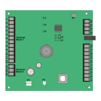
Lists and describes the function of each pin connector on the board.
Illustrates the wiring connections and board layout for installation.
Provides detailed electrical specifications including current draw and voltage inputs.
Details the procedure for correctly connecting the earth ground wire to the 5129 cover and base.
Describes how to use dry contact inputs for channel activation and trouble conditions.
Details wiring for active high or active low voltage inputs for channel activation.
Details wiring for active high voltage AC monitoring input.
Explains how to configure AC monitoring using a dry contact output.
Describes using a step-down transformer for AC monitoring.
Explains how to connect the 5230 annunciator to the 5128/29 using the specific cable.
Details the LCD display of the 5230 annunciator and the messages it shows.
Explains the function of the Power LED on the 5230 annunciator.
Describes the buzzer feedback provided by the 5230 annunciator for keystrokes and errors.
Details the different operating modes of the 5128/29 and their allowed actions.
Provides detailed instructions on how to navigate and make selections during step programming.
Explains the SIA (Security Industry Association) reporting format and its printout details.
Describes Silent Knight FSK and 4+2 reporting formats and their output.
Details the Radionics BFSK reporting format and its printout.
Explains 3/1 reporting formats from Silent Knight and Sescoa.
Details the Accu-Zone™ troubleshooting mode for diagnosing channel inputs and AC monitoring.
Lists and explains messages displayed on the 5230 annunciator for troubleshooting.
| Brand | SILENT KNIGHT |
|---|---|
| Model | 5128 |
| Category | Cell Phone |
| Language | English |