Do you have a question about the SILENT KNIGHT SK-2224 and is the answer not in the manual?
Detailed description of the SK-2224 fire alarm control panel features and specifications.
Contact information for Silent Knight technical support and sales for inquiries and parts ordering.
Compliance statement regarding FCC rules and potential radio interference.
UL listing and installation requirements for the SK-2224 control unit per NFPA 72.
Inventory list of components included in the SK-2224 shipping box.
List of optional accessories compatible with the SK-2224 Fire Alarm Control Panel.
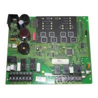
Diagram showing the SK-2224 circuit board with terminals, connectors, DIP switches, and LEDs.
Technical electrical ratings for the SK-2224 panel, including voltage, current, and power.
Recommended environmental conditions for operating and storing the SK-2224 panel.
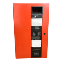
Guidelines and steps for securely mounting the SK-2224 control panel cabinet.
Step-by-step guide for assembling the SK-2224 control panel components inside the cabinet.
Guidelines for proper wiring to avoid induced noise and ensure panel operation.
Method for determining current draw and calculating standby battery requirements for installation.
Procedure for connecting the SK-2224 to the AC power source via a transformer.
Instructions for wiring two 12V batteries in series to provide a 24-volt equivalent.
Guidance on wiring for contact, two-wire, and four-wire smoke detectors and other initiating devices.
Information on the built-in alarm and trouble relays and their terminal configurations.
Details on the power-limited auxiliary power circuit and its terminal.
Instructions for configuring a door release using an ESL DH series door holder.
Procedures for installing optional accessories like the Serial Driver Board, LED Annunciator, and I/O Module.
Configure Enhanced Mode for zones using DIP switches SW1 and SW6 for pull stations and detectors.
Set DIP switches SW2 and SW7 to enable or disable alarm verification for zones.
Configure zone types (Fire alarm, Supervisory, No delay) using DIP switches SW3 and SW8.
Program alarm delay options (30, 60, 90 seconds) using DIP switches SW4, SW5, SW9, SW10.
Configure silencing for NAC circuits using DIP switches SW1 and SW3.
Set notification appliance pattern to ANSI or Steady using DIP switches SW2 and SW4.
Configure serial accessories like annunciators using DIP switch SW5 for the entire panel.
Set DIP switch SW6 for delayed NAC activation, noting dependency on cross alarm.
Enable or disable the cross alarm feature using DIP switches SW7 and SW8.
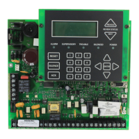
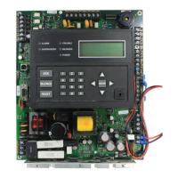
Explanation of the status indicators (LEDs) on the SK-2224 system board.
How to use the on-board keys (switches) for system operations like silencing and resetting.
List of smoke detectors compatible with the SK-2224, including two-wire and four-wire types.
List of notification appliances (horns, strobes, bells) compatible with the SK-2224.
| Model | SK-2224 |
|---|---|
| Type | Addressable Fire Alarm Control Panel |
| Zones | 24 |
| Compatibility | Silent Knight addressable devices |
| Operating Temperature | 32°F to 120°F (0°C to 49°C) |
| NAC Outputs | 4 |
| Maximum Signaling Line Circuits (SLCs) | 2 |
| Maximum Addressable Devices | 222 |
| Max Devices | 222 addressable devices |
| Output | 24 VDC |
| Communication Options | Ethernet |
| Relative Humidity | Up to 93% non-condensing |