Do you have a question about the SILENT KNIGHT 5700 and is the answer not in the manual?
Important warnings and precautions for installing the fire alarm system.
Provides a general overview of the 5700 system's basic features.
Explains the purpose and scope of the manual.
Lists compatible devices and accessories for the 5700 system.
Provides contact information for Silent Knight technical support and sales.
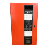
Instructions for securely mounting the main control panel cabinet.
Details on how to connect the panel to the AC power source.
Guidance on connecting the system's backup batteries.
Information on wiring the SBUS communication bus for modules.
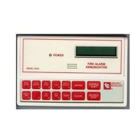
Steps for installing the optional 5860 remote annunciator.
Instructions for installing the 5824 printer interface module.
Details on installing the 5880 LED driver module.
Instructions for installing the 5865 series LED annunciators.
Steps for configuring system hardware modules.
Guidance on connecting the system to telephone lines for communication.
Information on installing the 5211 ground start relay.
How to wire notification appliances and auxiliary power circuits.
Information on using the panel's built-in relays.
Details on connecting to remote station monitoring systems.
Lists all compatible Signaling Line Circuit (SLC) devices.
Specifies the maximum number of SLC devices supported by the system.
Details the necessary wiring specifications for SLC devices.
Instructions for wiring heat and smoke detectors.
Procedures for assigning addresses to SLC devices.
FCC requirements and information for connecting the system to phone lines.
UL listing and installation requirements for various system configurations.
Lists the components included with the 5700 control panel.
Specifies environmental conditions to avoid for proper panel installation and operation.
Details the electrical ratings and terminal descriptions for the panel.
Guidelines for proper wiring to prevent noise and interference.
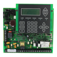
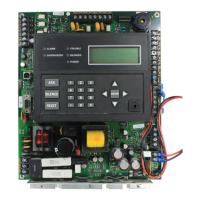
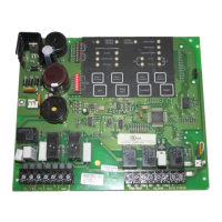
Illustrates the layout of the control panel's circuit boards and components.
Procedures for determining system current draw and battery requirements.
Automates system setup by scanning and configuring SLC devices.
How JumpStart determines and assigns input points and creates initial zones.
How JumpStart creates output groups and assigns output circuits.
Step-by-step guide for executing the JumpStart autoprogramming feature.
Explains the concept of mapping events to outputs for system behavior.
Using SKSS software for programming the control panel.
How to program the panel using the on-board or remote annunciator.
A quick reference guide to the program menu options and defaults.
Specific programming features and options required for UL 864 compliance.
Lists and describes the programming options for system modules.
Options for editing, adding, deleting, and viewing zone points and properties.
Options for defining and managing output groups for system responses.
How to change characteristics of individual input points like type and zone assignment.
Customizing software options affecting general system operation.
Instructions for running the JumpStart autoprogramming feature.
Information for programming computer account details for communication.
How to manage user access codes and profile functions.
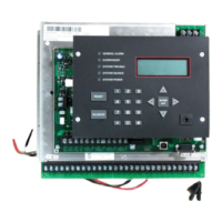
Description of the control panel's annunciator interface and its components.
Explains the function of the LCD display for messages and status.
Information on the banner message displayed when the system is in normal mode.
Overview of navigating the control panel's menu system.
Step-by-step instructions for fundamental system operations.
Describes how the panel behaves in different operational modes like Alarm, Supervisory, Trouble.
Details on configuring and managing releasing functions like Double/Single Interlock.
Explains the operation cycle of the smoke alarm verification feature.
Lists compatible receivers for the control panel's reporting functions.
Details the SIA and Contact ID reporting codes for dialer outputs.
Suggestions for resolving hardware problems encountered during installation or operation.
Lists common issues and their possible causes and suggested solutions.
Describes the panel's integrated tools for testing points and SLC devices.
Details earth ground fault resistance detection for various terminals.
A table for tracking module and sensor point information for installation records.
Lists compatible notification appliances for the fire alarm control panel.
Table of programmable characters and their numeric designators for naming points/zones.
| Model Number | 5700 |
|---|---|
| Category | Control Panel |
| Display | LCD |
| Power Supply | 120 VAC, 60 Hz |
| NAC Circuits | 4 |
| Event History Log | 1000 events |
| Weight | 12 lbs |