Do you have a question about the SILENT KNIGHT 5820XL and is the answer not in the manual?
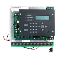
Describes the IntelliKnight 5820XL addressable fire control system, its packaging, and mounting.
Lists the hardware capabilities including SLC loops, output power, DACT, relays, and module support.
Details the software capabilities such as zones, output groups, and advanced smoke detector features.
Explains the manual's purpose as a reference for installation and operation tasks.
Defines key terminology such as SLC, Module, Input Point, Input Zone, and Output Point.
Lists compatible devices and modules for the IntelliKnight 5820XL system.
Provides contact information for technical support and ordering parts.
Discusses factors affecting fire detection and warning system performance.
Outlines requirements and recommendations for the installation and use of fire alarm devices.
Provides FCC information required for connecting the 5820XL to telephone lines.
Lists UL requirements applicable to all installations of the fire alarm system.
Specific UL requirements for systems connected to a central station.
Specific UL requirements for local protected fire alarm installations.
Specific UL requirements for systems using a DACT for remote monitoring.
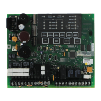
Lists the hardware components included with the IntelliKnight 5820XL system.
Specifies conditions to avoid and recommended environmental parameters for installation.
Details terminal functions, voltage, current ratings, and earth ground faults.
Provides guidelines to avoid induced noise and ensure proper wiring practices.
Guides the user through determining system current draw and battery requirements.
Details maximum battery standby load capacities based on battery size and standby hours.
Provides a checklist of tasks required for system installation with section references.
Instructions for securely mounting the control panel cabinet, including water damage prevention.
Guidance on connecting the control panel to the 120 VAC power source.
Procedures for wiring 12V batteries in series to create a 24-volt equivalent.
Information on calculating SBUS wire distances and wiring configurations (Class A and B).
Instructions for installing the optional Model 5860 Remote Annunciator.
Guidance on installing the 5815XL SLC expander to add addressable devices.
Instructions for installing the 5824 module to connect a printer.
Details on installing the 5880 LED driver board and its inputs/outputs.
Instructions for installing the 5865-3 and 5865-4 LED annunciator hardware.
Describes how to assign Module IDs using dipswitches for system modules.
Guidance on connecting the control panel to telephone lines for communication.
Information on using the six versatile Flexput circuits for various functions.
Procedures for connecting compatible UL listed two-wire smoke detectors.
Procedures for connecting compatible UL listed four-wire smoke detectors.
Explains how to use Flexput circuits for door holder, constant, or resettable auxiliary power.
Details the use of the panel's built-in trouble and programmable relays.
Instructions for connecting to remote station receivers and city boxes.
Catalog of addressable SLC devices compatible with the control panel.
Specifies the total capacity of addressable devices supported by the system.
General wiring guidelines for SLC devices, including wire gauge and resistance limits.
Information on wiring and addressing heat and smoke detectors.
Procedures for assigning addresses to detectors and modules using the FACP.
Overview of the automated system setup feature for faster installation.
Explains the concept of mapping events to outputs for system functionality.
Instructions for programming the panel using the SKSS software package.
Details on programming the system via the on-board or remote annunciator.
Steps to access and exit the system's programming mode.
A summary of program menu options, defaults, and section references.
Lists programming options restricted to meet UL 864 standards.
Lists the available modules that can be configured via the program menu.
How to modify module names, wiring class, and specific module features.
Step-by-step instructions for adding a new hardware module to the system.
Procedures for removing a module from the system configuration.
Options for editing, adding, deleting, and viewing zone points.
How to edit zone name, properties (type, sensitivity), and output mapping.
Options for managing output groups, including names and properties.
Options for changing individual input point characteristics after JumpStart.
Customizing software options affecting general system operation.
Configuration of up to four reporting accounts, including ID, format, and event reporting.
Settings for managing telephone line connections, dialing, and monitoring.
Mapping system trouble events to output groups and cadence patterns.
Settings for water flow delay, AC report delay, DST, clock format, and AC frequency.
Options to control strobe synchronization and report modes (zone/point).
Settings for alarm verification time and daylight saving start/end dates.
Customizing access codes for user profiles and panel functions.
Explains the components and layout of the control panel's annunciator.
Describes how to use the physical keys for accessing menus and operations.
Provides an overview of the control panel's menu structure and navigation.
Covers fundamental system operations like setting time, enabling points, and managing NACs.
How to access and display logged system events and clear the history buffer.
Procedure for initiating and ending a fire drill test on the system.
Tests the annunciator's LEDs, PZT, and LCD display for proper function.
Procedure for performing a system walk test to verify detector operation.
Steps to perform a manual test of the system's dialer communication.
How to silence audible alarms and troubles using the panel or external switch.
Verifies detector sensitivity and compliance with NFPA 72 standards.
Initiating communication with a computer for panel configuration uploads.
Options for printing event logs, history, and detector status reports.
Describes panel behavior in Normal, Alarm, Supervisory, Trouble, Silenced, and Reset modes.
Configuration options for Double Interlock Zone and Single Interlock Zone releasing.
Details conditions required for Pre-Alert and General Alarm/Release outputs.
Details conditions for Pre-Alert, General Alarm, and Release outputs with interlocks.
Illustrates the operational cycle of the smoke alarm verification feature.
Lists receiver manufacturers and models compatible with the control panel.
Details the SIA and Contact ID reporting codes sent by the panel for various events.
Lists common issues like double addresses, incorrect polarity, and missing SLC devices.
Recommendations for regular system inspection, testing, and maintenance procedures.
Utilizes panel features like SLC Device Locator and I/O Point Control for diagnostics.
Tool to locate a specific device on an SLC loop by its address.
Feature to locate up to eight SLC devices simultaneously on a single search.
Allows toggling outputs on/off and tripping input devices for testing.
Lists earth fault resistance values for terminal detection on the FACP.
A template to track the programming of SLC points, including module, address, and zone/group.
A chart for tracking the configuration of conventional output points (circuits).
Lists compatible notification appliances, including audio, visual, and type.
Lists compatible two-wire smoke detectors, their compatibility IDs, and # per loop.
Provides a table of programmable characters and their numeric designators for naming.
| Type | Addressable Fire Alarm Control Panel |
|---|---|
| Operating Temperature | 32°F to 120°F (0°C to 49°C) |
| Humidity | 10% to 93% non-condensing |
| Notification Appliance Circuits | 4 |
| Auxiliary Power Output | 24 VDC, 500 mA |
| Communication | RS-232 |
| Zones | 99 |
| NAC Circuits | 4 |
| Alarm Contacts | Form C |
| Trouble Contacts | Form C |
| Compatibility | Compatible with Silent Knight devices |
| Number of Circuits | 2 Signaling Line Circuits (SLC) |