


Do you have a question about the SILENT KNIGHT INTELLIKNIGHT 5820XL and is the answer not in the manual?
| Control Panel Type | Addressable Fire Alarm Control Panel |
|---|---|
| Power Supply | 120/240 VAC, 50/60 Hz |
| Battery Backup | 24 VDC, 18 AH |
| Event History Log | 1000 events |
| Operating Temperature | 32°F to 120°F (0°C to 49°C) |
| Humidity Range | 10% to 93% non-condensing |
| Display | 80-character LCD |
| Communication Ports | RS-232, RS-485 |
| Programming | Via PC software |
| Zones | 99 software zones |
| NAC Circuits | 4 built-in, expandable |
| Communication | Built-in digital communicator |
| Max Initiating Device Circuits (IDCs) | Not applicable |
| Communication Options | IP, Cellular |
| Certifications | UL, FM, CSFM |
Provides a general overview of the 5820XL/5820XL-EVS base system and its components.
Details the hardware capabilities of the 5820XL/EVS panel, including SLC loops, output power, and DACT.
Outlines the specific hardware features of the 5820XL-EVS, including the EVS-VCM and amplifiers.
Lists advanced software features such as drift compensation, JumpStart, and zone/group counts.
Explains the purpose and scope of the manual for installation and operation tasks.
Defines key terminology used throughout the manual, such as SLC, Module, Input Point, and Output Group.
Lists compatible products available for use with the 5820XL and 5820XL-EVS system.
Provides contact information for Silent Knight Technical Support and Sales departments.
Details FCC compliance information required for connecting the system to telephone lines.
Outlines general requirements and specific restrictions for UL installations.
Specifies general installation requirements, including wiring standards and device compatibility.
Lists specific programming and configuration requirements for central station systems.
Details requirements for installations using local protected fire alarm systems.
Outlines requirements for remote station protected fire alarm systems.
Lists the hardware components included with the 5820XL and 5820XL-EVS systems.
Provides essential environmental requirements for installing the control panel to prevent damage.
Details terminal descriptions and electrical specifications for the control panel's wiring.
Offers guidelines to avoid induced noise and ensure proper wiring practices for the system.
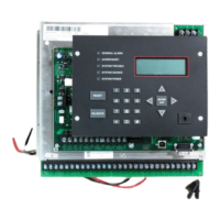
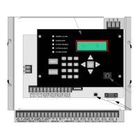
Illustrates the arrangement of circuit boards, housing, and annunciator for the 5820XL/5820XL-EVS assembly.
Guides users in determining current draw and standby battery needs for system devices.
Provides a chart listing essential tasks for installing the 5820XL/5820XL-EVS system.
Details procedures and considerations for mounting the control panel cabinet securely and safely.
Offers precautions to prevent water damage to the fire system cabinet during installation.
Instructions for safely removing the control panel assembly from its cabinet for repair.
Explains how to safely connect the AC power source to the control panel.
Provides instructions for connecting the system's backup batteries correctly.
Details the use and installation of the RBB Accessory cabinet for larger backup batteries.
Covers wiring calculations and configurations for SBUS modules.
Guides users in determining wire gauge and maximum wiring distances for SBUS modules.
Illustrates Class A and Class B wiring configurations for SBUS connections.
Instructions for installing the optional 5860 Remote Annunciator.
Describes flush and surface mounting procedures for the 5860 annunciator.
Details how to connect the 5860 remote annunciator to the main control panel.
Instructions for installing the 5815XL SLC expander module.
Explains how to connect the 5815XL module to the main panel assembly.
Instructions for installing the 5824 interface module for printer connectivity.
Guides users through configuring options for the 5824 module, including printer and output port settings.
Details the installation of the 5880 LED I/O module for driving LEDs and monitoring dry contacts.
Shows the layout of terminals and connectors on the 5880 board for LED and dry contact connections.
Explains how to connect the 5880 module to the main control panel via SBUS.
Provides instructions for wiring LEDs to the 5880 board's output connectors.
Details how to wire dry contact inputs on the 5880 board for monitoring switches.
Instructions for installing the 5865-3 and 5865-4 LED annunciator modules.
Explains how to connect the 5865 annunciator to the FACP via SBUS.
Describes mounting procedures for the 5865 annunciator in electrical boxes.
Explains how to configure system hardware modules added to the system.
Details how to use DIP switches to assign unique IDs to SBUS modules.
Instructions for connecting telephone lines to the panel for communication.
Describes the use and installation of Flexput™ I/O circuits for various applications.
Explains how to install conventional notification appliances in Class A and Class B configurations.
Provides wiring instructions for Class B notification appliances.
Provides wiring instructions for Class A notification appliances.
Explains how to install conventional initiating devices for Class A and Class B configurations.
Details how to connect conventional Class B switches to Flexput circuits.
Details how to connect conventional Class A switches to Flexput circuits.
Instructions for connecting UL listed 2-wire smoke detectors.
Wiring instructions for installing 2-wire Class B smoke detectors.
Wiring instructions for installing 2-wire Class A smoke detectors.
Instructions for connecting UL listed 4-wire smoke detectors.
Wiring instructions for installing 4-wire Class B smoke detectors.
Wiring instructions for installing 4-wire Class A smoke detectors.
Explains how to use Flexput circuits for auxiliary power applications.
Details the use of door holder power for fire door applications.
Describes the use of constant power for applications requiring a continuous auxiliary source.
Explains the use of resettable power for devices like beam detectors.
Covers the use of Sounder Sync Power for system sensor synchronization.
Discusses the panel's built-in programmable and trouble relays.
Explains the function and terminals of the dedicated Form C trouble relay.
Details the use and installation of the two Form C programmable relays.
Covers various remote station connection methods and modules.
Instructions for installing the Keltron Model 3158 for direct connection to a Keltron receiver.
Describes connecting the panel to a local energy municipal fire alarm box using the 5220 module.
Details how to implement NFPA 72 polarity reversal for control units.
Instructions for using the 5220 module for polarity reversal to report events.
Instructions for using the 7644 module for polarity reversal.
Instructions for wiring the SD500-ARM module for polarity reversal.
Details for wiring the MR-201/T relay for polarity reversal.
Describes connecting a remote station transmitter module using dry contacts.
Lists SK SLC detectors and modules compatible with the control panel.
Lists SD SLC detectors and modules compatible with the control panel.
Explains the maximum number of devices supported by the system based on SLC expanders.
Details general wiring requirements applicable to all SLC devices.
Provides wiring instructions for the 5815XL in a Class B configuration.
Provides wiring instructions for the 5815XL in Class A configurations.
Instructions for installing SK heat and smoke detectors.
Details how to set addresses for SK SLC devices using rotary dials.
Outlines security levels for communication, data storage, physical access, and access control.
Explains the JumpStart feature for automated system setup and initial programming.
Describes how JumpStart determines and assigns input points, zones, and output groups.
Details how JumpStart assigns output circuits to groups for the system.
Provides step-by-step instructions for running the JumpStart AutoProgramming feature.
Introduces the concept of mapping input points to zones and output points to groups.
Explains how input points are assigned to input zones for system configuration.
Demonstrates how to assign notification and relay output circuits to groups.
Details how to map zone events to output groups and patterns for specific responses.
Shows how LED points are mapped to zones and output groups for status indication.
Describes using the SKSS software for panel programming on-site or remotely.
Explains how to program the control panel using the on-board or remote annunciator.
Provides instructions for entering and exiting the panel's program menu.
Explains how to navigate through the panel's program menu screens.
Describes methods for making programming selections and entering data.
Details the function of various keys used within the program menu.
Lists programming options and restrictions required for UL 864 and UL 2572 compliance.
Details options available for configuring installed system modules.
Describes how to edit module ID, name, wiring class, and specific features.
Instructions for assigning English names to system hardware modules for easier recognition.
Explains how to modify options specific to a module's functionality.
Step-by-step guide for adding a new hardware module to the system.
Instructions for removing a module from the system configuration.
How to view a list of all modules currently installed in the system.
Covers programming options for zones, including editing, adding, deleting, and viewing zone points.
Details how to edit zone name, properties, output mapping, and accessory options.
Instructions for editing the name assigned to a zone.
Explains how to set alarm delay characteristics and heat detector sensitivity for a zone.
How to map output groups and cadence patterns to zone events.
Lists available cadence patterns for use with zones and system events.
Options for detectors used with Sounder or Relay bases.
Step-by-step instructions for adding a new zone to the system.
Instructions for removing a zone from the system configuration.
How to view the points associated with a specific zone.
Covers programming for output groups, including naming and properties.
Details how to program the name and properties of an output group.
Instructions for assigning a descriptive name to an output group.
Explains how to set latching, silencing, and other properties for output groups.
Step-by-step instructions for adding a new output group to the system.
Instructions for removing an output group from the system.
How to view the points assigned to a specific output group.
Used to create templates for mapping multiple zones to common output groups.
Covers programming for individual input and output points.
Instructions for programming points on the 5815XL module.
How to program points for internal or external power modules.
Instructions for programming points on various modules including 5880, 5865, and amplifiers.
How to program points for EVS-VCM and EVS-RVM modules.
Instructions for assigning descriptive names to points for easier identification.
Covers customization of software options affecting general system operation.
Details configuration of up to four reporting accounts for event reporting.
How to edit account numbers, reporting formats, and event reporting settings.
Setting the time for automatic dialer test reports.
Configuration options for the system's phone lines.
Setting dialing prefixes for PBX dial-out codes or pauses.
Configuring the number of rings before the panel answers a computer call.
Selecting the dialing method (TouchTone or Pulse) for phone lines.
Setting the pulse ratio for rotary dialing options.
Enabling or disabling the line monitor for each phone line.
Configuring the feature to prevent answering machines from interfering with communication.
Mapping system trouble events and alarm cadences to output groups.
Mapping various system trouble events to output groups and cadence patterns.
Setting special cadence patterns for fire drill and auxiliary alarm events.
Configuring water flow delay, alarm verification, and clock settings.
Programming a delay for water flow switches to avoid false alarms from brief pressure changes.
Setting the time for the alarm verification feature to confirm alarm conditions.
Adjusting the delay before a low AC report is sent to the central station.
Selecting the system clock display format as AM/PM or military time.
Selecting the AC line frequency for time calculation.
Configuring options for strobe synchronization, auto display, reporting, plex door, and single key acknowledge.
Enabling synchronized strobes to flash when the system is silenced.
Automatically displaying the oldest unacknowledged event on the panel after inactivity.
Selecting whether events are reported by zone or by individual point.
Instructions for turning the plex door hardware option on or off.
Allows acknowledging events with a single key press.
Configuring automatic daylight saving time adjustments.
Enabling or disabling the automatic DST adjustment feature.
Adjusting the week and month for DST start and end dates.
Customizing the banner message displayed on the panel LCD in normal mode.
Configuring the panel to accept SD or SK protocol SLC devices.
Instructions for running JumpStart to automatically program the system after device installation.
Programming computer account information for communication with the SKSS software.
Managing user access codes and profiles for panel functions.
Editing user names, access codes, and panel functions for each profile.
Instructions for editing user names within profiles.
Instructions for changing access codes for user profiles.
Selecting panel functions accessible by each user profile.
Configuring settings related to the Emergency Voice System (EVS).
Procedures for programming custom messages into the EVS-VCM.
Instructions for connecting a PC for message management via EVS Message Manager Software.
Options for recording messages using the EVS-VCM microphone or PC sound card.
Programming messages, tones, and delays for EVS voice commands.
Configuring system-wide EVS options.
Enabling or disabling the Emergency Voice System on the panel.
Setting the priority level for different voice commands.
Mapping EVS messages to output groups or templates for voice events.
Details on how to edit command mapping for voice commands.
Configuring various timers for EVS events, including control lockout and auto reset.
Lists the types of timers included in the EVS system options.
Accessing the menu for configuring EVS timers.
Lists the default user and installer access codes for the control panel.
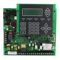
Describes the components of the control panel's annunciator, including LEDs and LCD display.
Explains the function of the LCD display for showing system messages and prompts.
Describes the banner message displayed on the panel in normal mode.
Explains how to use the key for accessing the Main Menu and operating the panel.
Overview of how to navigate and operate the control panel using its menu system.
Provides a brief overview of the options available in the Main Menu.
Instructions on how to navigate through the panel's menus and select options.
Covers fundamental operations such as setting time/date, managing points, and viewing history.
Steps for setting the system's current time and date.
Instructions for disabling or enabling individual points on the system.
How to disable or enable Notification Appliance Circuits using templates.
How to disable or enable Notification Appliance Circuits using groups.
Instructions for disabling or enabling specific zone points.
How to display and review events stored in the panel's event history.
Steps to clear the panel's event history buffer.
Instructions for initiating and ending a fire drill test.
Testing the annunciator LEDs, PZT, and LCD display for proper function.
Steps for performing a walk test with or without reporting to the central station.
Performing a test of the system's dialer communication.
How to silence active alarms or trouble conditions.
Instructions for resetting active alarms on the system.
Monitoring smoke detector sensitivity levels for NFPA 72 compliance.
Displaying the status and troubleshooting information for a specific point.
Navigating to view active alarms, supervisories, or troubles on the system.
Accessing panel model, serial number, and software version information.
Options for resetting specific system components like the dialer or DSP USB.
Procedure to reset the system's dialer.
Procedure to reset the DSP controller and USB interface logic.
Instructions for initiating communication with a computer for uploads or downloads.
Options for printing system event logs, detector status, and configuration.
Describes how the panel behaves in different operational modes like Normal, Alarm, and Trouble.
Details the setup and operation of releasing functions, including interlock zones.
Explains the operation of a single interlock zone for releasing functions.
Explains the operation of a double interlock zone for releasing functions.
Illustrates the operation cycle of the smoke alarm verification feature.
Introduces the EVS series controls, their compliance, and integration with fire alarm systems.
Describes the Local Operation Control (LOC) interface for managing EVS functions.
Explains the functionality of keys and LEDs on the EVS-VCM and EVS-RVM modules.
How to use the EVS Control Key to gain or relinquish EVS control.
Indicates the status of EVS Control in the system.
Used to deliver verbal messages to all voice groups.
Used to deliver verbal messages to non-activated output groups.
Used in Message Mode to select and play EVS messages.
Indicate active EVS messages and LOC control status.
Toggle which output areas are active for messages or microphone paging.
Indicate which output areas are active for microphone paging or system events.
Explains the conditions governing how EVS Control is obtained.
Describes the priority levels assigned to LOCs for gaining EVS Control.
Governs when an LOC can gain EVS Control from another LOC of the same priority.
Requires specific user profiles to gain EVS Control.
Allows manual activation of EVS events and emergency paging.
How to switch between modes for message playback or microphone paging.
Dynamically activating/deactivating output areas for notification without system mapping.
Allows users to toggle output areas for microphone paging.
Allows users to select messages and toggle output areas for playback.
How to generate an EVS event and speak a custom message using the microphone.
Procedures for passing EVS Control between LOCs with the same priority.
How to exit the LOC EVS interface.
How to relinquish EVS Control back to the system.
Procedures for resetting the fire or emergency system from an LOC.
How user profiles and access codes affect EVS Control acquisition.
Provides the highest priority user with the ability to override EVS Control rules.
Describes using EVS 5880 modules and input points for EVS inputs.
How EVS points activate outputs and are placed into an alarm state.
Explains the use of VCM/RVM input points for triggering external audio.
Details the EVS (1-8) 5880 module and its unique options.
Information on the EVS 5880 module, its inputs, and programming capabilities.
How to enable EVS settings and priority for the 5880 module.
Covers device priority assignment and LOC association for EVS devices.
Step-by-step instructions for adding a new Local Operation Control (LOC) to the system.
Details how to edit LOC features like priority, gain, and associated keypad.
Describes assigning priority levels (Low, Normal, High) to LOCs.
How to associate an annunciator with an EVS-VCM or EVS-RVM module to create an LOC.
Instructions for adding and editing amplifier settings.
Step-by-step guide for adding a new amplifier module to the system.
How to edit amplifier settings such as ID, name, and voltage.
Explains how event activations are handled by the control panel based on priority.
How the panel integrates fire and emergency systems to determine output control.
Temporarily disengages output activations to avoid conflicting messages.
Assigns priority levels to event types to determine system response.
How to view active alarms, troubles, and supervisory signals on the LCD display.
Details microphone functionality for live paging and custom EVS events.
Describes the capabilities of microphones for live fire system or EVS paging.
How to generate an EVS event and speak a custom message via microphone.
Conditions under which a fire page can occur.
Conditions under which an emergency page can occur.
Steps for using the microphone for general paging when no events are active.
Instructions for recording and managing custom messages for the EVS system.
How to load customized messages using the Aux Audio Input.
Steps for recording messages using the onboard microphone.
Procedures for erasing stored user messages from memory slots.
How to use the software utility to download and manage EVS messages.
Explains the priority table and rules governing EVS events.
Lists the rules that determine the priority of EVS events and system interactions.
How to define output groups as voice or non-voice for mapping to switches and LEDs.
Mapping EVS events to activate output groups automatically or manually.
Mapping EVS events to output groups similar to fire system event mapping.
How voice aux inputs are prioritized dynamically based on system configuration.
Mapping EVS messages to output groups or templates for voice events.
Details on how to edit command mapping for voice commands.
Configuring various timers for EVS events, including control lockout and auto reset.
Lists the types of timers included in the EVS system options.
Accessing the menu for configuring EVS timers.
Lists compatible receivers for the control panel.
Details reporting codes sent by the panel for SIA and Contact ID formats.
General suggestions for troubleshooting hardware problems with the control panel.
Lists common problems and their suggested causes or solutions.
Recommendations for regular system inspection, testing, and maintenance.
Usefulness of event history for tracking or recalling trouble conditions.
Describes built-in tools for testing and troubleshooting points and SLC devices.
Tool to locate a specific device on an SLC loop.
Feature to locate up to 8 devices on a single search.
Allows toggling outputs on/off and tripping input devices for testing.
Lists earth fault resistance detection values for applicable terminals on the FACP.
Table for recording detector and module points installed on the SLC loop.
Chart to track configuration of conventional output points (circuits).
Lists notification appliances compatible with the fire alarm control panel.
Lists compatible two-wire smoke detectors organized by manufacturer.
Lists compatible 520Hz signaling speakers.
Lists compatible 520Hz low frequency sounder bases.
Table of programmable characters and their numeric designators for naming points or zones.